
Low cogging makes a slotless inrunner BLDC motor suitable for low-speed metering when drive regulation, pump hydraulics, and thermal capacity are matched. Smoother motor torque can reduce rotational disturbances.
It cannot guarantee dose accuracy. Actual delivered volume depends on displacement, leakage, fluid compliance, pressure variation, startup behavior, and calibration. Motor construction and electrical characteristics also require confirmation.
How Does a Slotless Inrunner BLDC Motor Improve Low-Speed Torque Smoothness?
A slotless inrunner motor can reduce one important source of rotational disturbance, particularly when a metering pump operates slowly or delivers small quantities through repeated cycles.
Gian Transmission offers customizable inrunner brushless DC motors, including slotless and slotted configurations. The actual construction and operating characteristics of any selected model require confirmation.
Slotless Stator Design and Reduced Cogging Torque
An inrunner BLDC motor places the rotating magnetic assembly inside the stationary stator. In conventional slotted designs, stator teeth and slots influence magnetic interaction as the rotor turns.
Cogging torque develops from changes in magnetic reluctance as rotor magnets move relative to stator teeth. This interaction can create position-dependent resistance to rotation without applied winding current.
Slotless construction removes the conventional tooth-slot geometry, substantially reducing this source of cogging. The benefit becomes particularly relevant when small torque disturbances can affect low-speed motion.
However, reduced cogging does not mean that electromagnetic torque remains perfectly constant. Winding distribution, commutation timing, current ripple, and rotor position estimation can still introduce variations.
Smooth Motor Torque Versus Stable Pump Rotation
Torque disturbances can produce speed fluctuations when the combined inertia of the motor and pump cannot sufficiently smooth them. Their effect depends on operating speed and load characteristics.
In a metering pump, smoother shaft rotation may reduce motor-induced flow disturbances. The actual improvement depends on pump geometry, fluid behavior, and the duration of each dispensing cycle.
Three different characteristics should be considered separately:
- Cogging torque: Position-dependent magnetic torque associated with stator and rotor geometry.
- Electromagnetic torque ripple: Torque variation caused by electrical excitation, commutation, and winding characteristics.
- Delivered-flow variation: Changes in actual fluid output caused by mechanical motion and hydraulic conditions.
Although related, each describes a distinct aspect of system behavior. A motor may rotate smoothly while pump leakage, trapped gas, or valve behavior still causes inconsistent delivery.
Which Electrical Characteristics Determine Metering Pump Motor Suitability?
Motor selection requires more than comparing rated power and nominal speed. Electrical constants determine whether the motor can generate the necessary torque within the available supply and driver limits.
The brushless DC motor configurations offered by Gian Transmission provide a starting point for discussing winding options, voltage requirements, and mechanical integration.
Torque Constant and Pump Load Requirements
The torque constant describes the relationship between electromagnetic torque and torque-producing current under a defined measurement convention. A higher constant generally provides more torque for the same current.
For a metering pump, required shaft torque depends on displacement, differential pressure, friction, and mechanical losses. Startup conditions may differ substantially from steady rotation.
With an ideal positive-displacement mechanism, theoretical pressure-related torque increases with displacement and pressure differential. Actual shaft demand also includes friction and design-specific losses.
The motor must supply sufficient torque at the lowest operating speed without exceeding its allowable current or thermal limits. Peak capability alone cannot establish continuous operating suitability.
Back EMF and Operating Speed Range
Back electromotive force increases with rotor speed. The driver must provide sufficient voltage to overcome back EMF and the electrical voltage drops associated with winding current.
If available voltage becomes insufficient, the current controller may lose its ability to maintain commanded torque. This limits performance even when the motor has adequate mechanical capability.
Torque constant and back-EMF constant are physically related. Their numerical relationship depends on consistent units and definitions, including phase quantities, waveform conventions, and peak-versus-RMS values.
Motor data should therefore identify the measurement convention. Comparing constants from different specifications without checking their definitions can produce incorrect winding or driver choices.
Winding Resistance, Inductance, and Electrical Losses
Winding resistance determines part of the electrical heating generated by motor current. Resistance also changes with temperature, affecting voltage demand and operating losses during extended pumping.
Inductance influences how rapidly winding current changes. Many slotless designs have relatively low inductance, although the actual value depends on winding geometry and magnetic construction.
Low inductance permits rapid current response but can also increase current ripple under PWM excitation. Their combined electrical behavior matters more than either characteristic considered in isolation.
| Motor Characteristic | Effect on Pump Operation | Engineering Selection Consideration |
| Torque constant | Determines torque-producing current requirements | Check startup and continuous load demands |
| Back-EMF constant | Influences voltage demand across the speed range | Verify supply and driver voltage margin |
| Winding resistance | Contributes to copper losses and heating | Check current and operating temperature |
| Winding inductance | Influences current ripple and electrical response | Match PWM operation and current regulation |
| Cogging torque | Can disturb low-speed rotational motion | Evaluate its significance relative to the pump load |
Why Does a Slotless BLDC Motor Require Careful Driver Matching?
Reducing cogging torque addresses a magnetic source of motion disturbance. It does not eliminate the electrical challenges involved in producing controlled torque through a switching motor driver.
Low Inductance and PWM Current Ripple
A motor driver commonly regulates winding voltage using pulse-width modulation. During switching intervals, the winding current rises or falls according to the applied voltage and electrical impedance.
With relatively low inductance, current can change rapidly during each switching cycle. Excessive ripple may produce additional winding heating and periodic variations in electromagnetic torque.
The effect depends on supply voltage, switching frequency, winding characteristics, operating current, and control strategy. A slotless motor should not automatically be considered electrically smoother than a slotted alternative.
Driver compatibility should be checked using actual winding data and representative current measurements. A motor that rotates smoothly without a load may behave differently under pressure-dependent pump torque.
Current Sensing Accuracy and Control Bandwidth
Current sensing gives the controller information needed to regulate electromagnetic torque. Measurement noise, resolution, sampling delay, and switching interference can all affect the quality of this feedback.
Current-loop bandwidth determines how quickly the controller can respond to disturbances. Insufficient bandwidth may allow substantial current errors, while excessive or poorly tuned bandwidth can introduce instability.
Suitable bandwidth also depends on switching frequency, electrical time constants, processing delays, and the selected control algorithm. Faster control is not automatically better without adequate stability margins.
Engineers should inspect current waveforms during steady running, acceleration, and pressure changes. Measurements should identify whether observed fluctuations originate from the driver, motor, or mechanical loading.
PWM Frequency and Driver Electrical Limits
Increasing PWM frequency can reduce switching-related current ripple under otherwise comparable conditions. Raising the switching rate may reduce current ripple, but it also increases switching losses and driver operating demands.
The selected frequency must be compatible with the motor’s electrical characteristics and the driver’s thermal design. Current-sampling timing and control-loop configuration also require coordinated adjustment.
Driver specifications should be reviewed for several operating limits:
- Supply voltage: Available voltage throughout the required speed and load range.
- Continuous current: Current capability during sustained pumping without unacceptable heating.
- Peak current: Permitted transient current during startup and load changes.
- Current measurement: Suitable sensing resolution, range, and sampling behavior.
- Protection functions: Appropriate responses to excessive current, stalls, and thermal faults.
No single PWM frequency or controller setting is appropriate for every slotless motor. Settings should be established through electrical analysis and measurements on the intended motor-driver combination.
How Do Position Feedback and Startup Control Affect Precision Metering?
Metering applications frequently require reliable operation at low speed or from standstill. Rotor-position information becomes important because incorrect commutation can produce unstable torque or failed starts.
Sensored Control for Low-Speed Operation
Hall sensors identify rotor magnetic positions and support electronic commutation. Encoders can provide finer position information, depending on their resolution, mounting arrangement, and signal-processing method.
For repeated short dispensing cycles, appropriate position feedback can help establish predictable startup behavior. It may also support accurate shaft-revolution counting when the controller uses that information correctly.
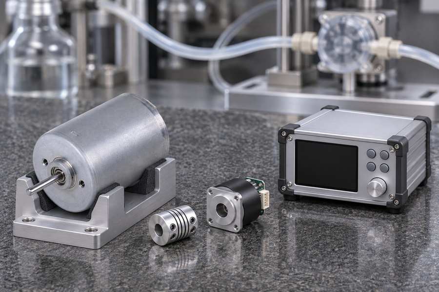
Basic Hall commutation feedback should not be confused with high-resolution position measurement. The required feedback depends on whether the system regulates approximate speed, precise angular motion, or delivered volume.
Sensorless Control and Low-Speed Limitations
Conventional sensorless BLDC control can estimate rotor position from back EMF. Because back EMF decreases with speed, this approach becomes difficult near standstill.
Open-loop startup may be used before sufficient electrical information becomes available. However, a pump starting against pressure can require torque that the initial commutation sequence does not reliably provide.
More advanced sensorless estimators may improve low-speed performance, but their suitability depends on motor characteristics and controller implementation. Their capabilities must be demonstrated under the intended load conditions.
Startup Torque, Acceleration, and Stall Protection
A metering pump may begin operating while pressure remains in its discharge line. Static friction, valve resistance, and fluid loading can create a different torque requirement from steady running.
Controlled acceleration should prevent excessive current while maintaining sufficient torque for reliable motion. Deceleration and stopping behavior can also affect the final delivered quantity.
Validation should include loaded starts, repeated stops, interrupted cycles, and fault recovery. The controller must distinguish successful dosing from stalled motion or an incomplete dispensing sequence.
If a cycle is interrupted, the system should retain enough information to determine whether restarting would repeat part of the commanded dose. That decision requires application-specific control logic.
How Do Pump Hydraulics Affect Actual Metering Accuracy?
The pump converts shaft motion into fluid movement. This conversion introduces hydraulic effects that cannot be removed simply by selecting a motor with low cogging torque.
Pump Displacement and Theoretical Delivered Volume
For an applicable positive-displacement pump, theoretical delivery is related to displacement per revolution and the number of shaft revolutions. Actual output can differ because of leakage and other effects.
Illustrative calculation: Suppose a hypothetical pump has a theoretical displacement of 0.10 mL per revolution. Fifty complete revolutions would correspond to 5.0 mL of theoretical displacement.
This calculation does not establish actual outlet delivery. Internal leakage, trapped gas, fluid compression, valve behavior, and pressure changes can alter the measured volume.
For a selected pump, engineers should establish its displacement characteristics and relevant operating limits before deciding how motor revolutions will be converted into dosing commands.
Internal Leakage, Slip, and Backpressure
Internal leakage allows part of the displaced fluid to move through unintended internal paths rather than reach the outlet. The amount depends on pump design and operating conditions.
Increasing differential pressure can increase leakage in susceptible pump mechanisms. Fluid viscosity, component clearances, wear, and temperature may also influence the resulting volumetric efficiency.
Backpressure can simultaneously increase shaft torque demand. The motor and driver must respond to that load while the calibration accounts for any change in actual delivery.
Maintaining constant rotational speed therefore does not guarantee constant flow. A motor may follow its speed command accurately while hydraulic losses produce measurable dosing differences.
Fluid Compliance, Entrained Gas, and Flow Pulsation
Fluid systems contain elements that can store and release energy under pressure. Flexible tubing, elastic pump components, and trapped gas can delay the relationship between shaft motion and outlet flow.
Entrained gas is particularly important because compression may absorb part of the pump’s displacement before the fluid reaches the dispensing point. The effect can vary between cycles.
Flow pulsation can also originate from pump chamber geometry, valve switching, and periodic displacement. Reduced motor cogging cannot eliminate these hydraulic sources of variation.
Engineers should examine the complete fluid path, including inlet restrictions, discharge tubing, valves, and dispensing nozzles. Testing only the motor cannot characterize these influences.
Motor Motion Accuracy Versus Delivered Dose Accuracy
Motor positioning accuracy describes how closely actual shaft motion follows a commanded movement. Delivered dose accuracy describes the difference between intended and measured fluid quantity.
These measurements answer different questions. Accurate shaft rotation may support repeatable theoretical displacement, but hydraulic conditions determine how much fluid actually reaches the specified measurement point.
Calibration should compare motor commands with delivered quantities under defined conditions. Depending on the application, suitable measurement methods may include gravimetric measurement or a properly validated flow sensor.
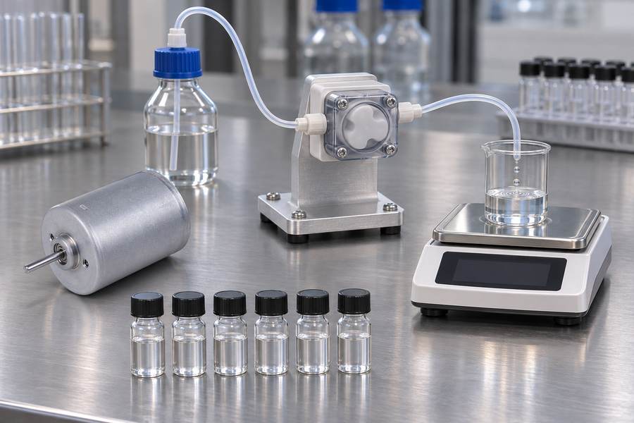
The chosen method must account for measurement uncertainty, fluid properties, and collection procedures. A repeatable motor command is not sufficient evidence of accurate dosing.
What Thermal and Mechanical Conditions Must a Slotless Inrunner Motor Meet?
Electrical suitability does not establish whether a motor can operate throughout the required duty cycle. Heating, coupling conditions, and installation constraints must also be evaluated.
Continuous Torque, Heat Generation, and Duty Cycle
Winding current produces resistive losses that increase motor temperature. Additional losses depend on motor construction, operating speed, magnetic behavior, and the selected control method.
A pump operating continuously may reach a different thermal condition from one delivering short doses intermittently. Repeated startup currents can also contribute to heating.
Engineers should compare continuous and transient torque demands with the motor’s verified operating limits. A short-duration torque rating must not be treated as continuous capability.
Motor Cooling and Installation Environment
Heat transfer depends on housing construction, surrounding airflow, mounting contact, and ambient temperature. An enclosed pump assembly may have different thermal behavior from an exposed motor.
Slotless and inrunner construction do not independently guarantee superior cooling. Thermal performance must be established for the actual motor geometry, winding configuration, and installation.
Representative testing should monitor accessible motor temperatures and use an approved method to evaluate winding temperature where required. Results should be compared with documented thermal limits.
Shaft Alignment, Coupling, and Mechanical Integration
The motor shaft must connect to the pump without introducing excessive misalignment or unintended bearing loads. Coupling selection should consider the actual geometry and transmitted torque.
Misalignment can increase vibration, friction, and mechanical wear. These effects may also change the torque required to maintain motion at low operating speeds.
Motor mounting and pump sealing require separate checks. A suitable motor housing does not establish fluid compatibility or prevent leakage from entering sensitive electrical components.
Approved drawings should define shaft geometry, mating dimensions, mounting datums, and allowable loads. Verify the installed fit and alignment against the approved drawing, since individual part dimensions cannot establish assembly accuracy.
What Customization Options Should Be Confirmed With Gian Transmission?
Gian Transmission describes customization options for inrunner motors, including dimensions, shaft arrangements, windings, and voltage. Project suitability still requires agreement on the specific motor construction and specifications.
Electrical Configuration and Motor Specifications
Winding selection should reflect the available supply voltage, required speed range, and expected torque demand. Resistance, inductance, torque constant, and back EMF should be reviewed together.
Request electrical data under clearly stated measurement conditions. Temperature, phase connection, and parameter definitions should be identified wherever they affect engineering comparisons.
The selected driver must support the actual winding characteristics. Customization should not be considered complete until the motor-driver combination meets the specified operating requirements.
Mechanical Interfaces and Feedback Requirements
Motor diameter, body length, shaft dimensions, and mounting arrangements should be compared with the pump assembly drawing. Coupling and bearing-load considerations must be included.
Feedback requirements should identify whether Hall sensors, an encoder, or validated sensorless operation is necessary. The selection should follow the required startup and dosing behavior.
Requested customization features must be confirmed individually. Published customization categories do not automatically establish the availability of every mechanical, electrical, or environmental configuration.
Confirming the Actual Motor Construction
An inrunner motor is not necessarily slotless. Rotor placement and stator slot construction describe different design characteristics, so both must be identified separately.
For example, the BLDC4266 is identified as an inrunner model, but its slotless construction should not be assumed without specific confirmation from Gian Transmission.
Before approving a candidate motor, request documentation identifying its stator topology, winding characteristics, feedback arrangement, and operating limits. Unverified efficiency or precision claims should not influence acceptance.
How Should Motor and Pump Performance Be Validated Before Selection?
Validation must establish whether the complete motor-driven pumping system produces the required fluid quantity. Motor measurements alone cannot demonstrate dosing accuracy or repeatability.
Define the Required Dosing Performance
Acceptance requirements should identify the intended dose, operating flow range, pressure conditions, fluid properties, and relevant environmental temperatures. Identify the exact fluid collection or measurement location.
Set separate acceptance criteria for deviation from the target dose and variation between repeated doses. Accuracy concerns deviation from the required dose, while repeatability concerns variation between repeated measurements under defined conditions.
The test plan should state the number of cycles, measurement method, and acceptable variation. These values must come from application requirements rather than assumed motor capability.
Test Low-Speed Stability and Loaded Startup
Low-speed tests should observe actual shaft movement while recording relevant electrical behavior. Where practical, current measurements can help identify drive-induced torque disturbances.
Startup testing should include representative backpressure and friction conditions. Successful unloaded rotation is not sufficient evidence that the pump will start reliably during normal operation.
Repeated starts and stops should be examined for missed motion, unintended reverse movement, excessive current, and incomplete cycles. Fault responses must preserve correct dose accounting.
Calibrate Delivered Volume Across Operating Conditions
Calibration should compare commanded revolutions or operating time with measured outlet delivery. The procedure must identify fluid temperature, pressure conditions, and the measurement method.
Evaluate performance across the specified speed and load conditions, including the relevant operating limits. Pressure-dependent leakage or changing fluid viscosity may create different calibration behavior.
Where calibration changes significantly across conditions, the control system may require compensation or direct fluid feedback. Any correction should be validated independently of the data used to establish it.
Verify Thermal Duty and Dose Repeatability
Thermal testing should reproduce the intended operating cycle, including relevant startup events and steady pumping periods. Temperature measurements must be evaluated against approved motor limits.
Delivered-volume testing should use repeated cycles at representative conditions. Results should distinguish systematic dose error from cycle-to-cycle variation rather than combining them into one performance figure.
| Validation Item | Measurement Method | Main Engineering Purpose |
| Low-speed stability | Shaft speed or position measurement with current observation | Identify irregular motion and electrical disturbances |
| Loaded startup | Record startup response under defined pressure conditions | Confirm reliable motion from standstill |
| Backpressure variation | Measure delivered volume at representative pressure points | Identify pressure-dependent dosing changes |
| Delivered-volume calibration | Compare measured delivery against commanded motion | Establish the operating calibration relationship |
| Repeated dosing | Measure multiple consecutive doses under controlled conditions | Evaluate dose repeatability |
| Thermal duty | Monitor motor temperature during representative operation | Verify sustained operating suitability |
When Is a Slotless Inrunner BLDC Motor the Right Choice for a Precision Metering Pump?
Applications That Can Benefit From Reduced Cogging
Slotless construction is worth considering when cogging contributes materially to low-speed motion disturbances. Its value is greatest when reducing that disturbance improves a measurable system requirement.
The selected motor must still produce sufficient torque, start reliably, and operate within electrical and thermal limits. The driver must regulate current effectively despite potentially low winding inductance.
The decision should be based on representative pump testing, not motor topology alone. A smoother motor may offer limited dosing improvement when hydraulic variation dominates the error.
When a Conventional Slotted BLDC Motor May Be More Suitable
A slotted motor may be appropriate when its torque characteristics, winding properties, dimensions, and thermal capabilities better match the application. Construction type alone does not establish superiority.
System cost and controller compatibility also matter. A motor requiring more demanding current regulation may introduce additional design work without a corresponding improvement in measured delivery.
Compare candidate motors using the same pump, fluid, pressure range, duty cycle, and acceptance method. Differences observed under unrelated operating conditions cannot establish an equivalent technical comparison.
Key Criteria for Final Motor Selection and Acceptance
Before approving the motor, engineering and purchasing teams should establish a common record of design requirements, verified specifications, inspection results, and system-level acceptance evidence.
- Motor construction: Record the confirmed stator topology, model identification, winding configuration, and approved drawing revision.
- Torque capability: Document required startup and continuous torque, operating speeds, and allowable motor current.
- Driver compatibility: Record supply conditions, PWM settings, current-sensing configuration, controller tuning, and observed electrical behavior.
- Position feedback: Identify the feedback method and retain evidence of reliable startup, stopping, and low-speed operation.
- Hydraulic conditions: Record pump displacement, test fluid, differential pressure, temperature, and relevant tubing or valve arrangements.
- Thermal performance: Retain representative temperature measurements, operating duration, and applicable acceptance limits.
- Dose calibration: Preserve calibration data linking commanded motion to measured delivered volume across the required operating range.
- Acceptance results: Record actual dose errors, repeatability results, measurement uncertainty, and any deviations requiring correction.
Each acceptance record should identify the equipment configuration, test conditions, measurement instruments, and responsible reviewer. Following a motor, driver, or pump modification, document which validation procedures need to be repeated.
Release the motor-pump assembly for its intended application only after the documented electrical, mechanical, thermal, and delivered-volume acceptance criteria have been satisfied.