
Separating rotor-bell imbalance from propeller imbalance requires staged inspection and vibration tests of the bare motor, mounting adapter, and complete propeller assembly. Each comparison needs consistent instrumentation and repeatable mounting.
Matched RPM does not reproduce identical thrust, current, temperature, or structural loading. Phase-based interpretation also depends on a stable vibration transfer function between test configurations.
What Should You Inspect Before Comparing Motor and Propeller Vibration?
An outrunner motor has a stationary inner stator and an external rotating bell. The bell, shaft, adapter, and propeller can each contribute to measured vibration.
Before interpreting vibration data, engineers should inspect mechanical interfaces and identify conditions that could produce eccentric rotation, looseness, or inconsistent component alignment.
Inspect the Rotor Bell, Shaft, and Bearing Conditions
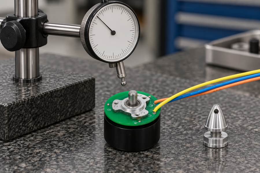
Inspect runout and mechanical condition before attributing vibration to imbalance. This unpowered preparation view shows separate inspection equipment; it does not demonstrate a completed measurement or a specified tolerance.
The rotor bell contains rotating magnetic components and forms part of the motor’s rotating assembly. Uneven mass distribution can produce periodic centrifugal forces during operation.
However, excessive vibration does not automatically indicate rotor-bell mass imbalance. Shaft misalignment, bearing damage, mechanical looseness, and geometric runout can produce similar measurement patterns.
For an outrunner brushless DC motor, inspection should establish the relevant rotating surfaces, bearing arrangement, and mounting interfaces before selecting measurement locations.
- Rotor-bell condition: Inspect accessible surfaces for deformation, impact damage, interference, or evidence of looseness without disturbing the manufacturer’s approved rotating assembly.
- Shaft runout: Measure radial runout at specified reference locations using a suitable indicator and controlled shaft rotation under safe, deenergized conditions.
- Bearing condition: Check for abnormal radial play, axial movement, rough rotation, and signs of mechanical damage using application-approved inspection methods.
- Mounting security: Verify that stationary supports, fasteners, and mounting faces remain secure and properly seated throughout the planned measurement sequence.
Radial runout describes geometric variation during rotation, whereas mass imbalance describes an uneven rotating mass distribution. Geometric runout and rotating mass imbalance can occur together, but they describe different mechanical conditions.
Record the measurement datum, indicator position, and total indicated runout. Evaluate the measured results against approved mechanical specifications instead of assuming that one tolerance applies to every assembly.
Where bearing clearance influences the reading, document the measurement method and applied contact force. Otherwise, apparent shaft eccentricity may partly reflect bearing movement.
Inspect the Propeller and Mounting Adapter
A mounting adapter introduces another rotating interface. Its eccentricity, seating condition, and mechanical retention can affect vibration even when the bare motor performs acceptably.
Inspect the adapter’s locating diameter, mounting faces, and approved retention features. Contamination or uneven contact can shift the propeller center relative to the shaft axis.
Propeller inspection should address visible blade damage, hub integrity, and mounting fit. Differences in blade geometry can also generate aerodynamic excitation independent of mass imbalance.
- Hub fit: Confirm that the propeller locating surfaces match the approved adapter and do not permit unintended radial or angular movement.
- Fastener retention: Follow the specified tightening sequence, preload requirements, and locking method for the actual shaft and propeller interface.
- Assembly condition: Reject damaged or incompatible parts before powered testing and document any irregularity requiring supplier review.
Powered propeller testing requires a suitable guarded facility, controlled access, and an approved operating procedure. Inspection findings should determine whether the assembly is safe to test.
How Can You Compare the Bare Motor, Adapter, and Propeller?
The most useful diagnostic approach introduces rotating components in separate stages. Each stage provides additional evidence while preserving a clearly documented configuration.
Testing only the complete assembly cannot reliably distinguish rotor-bell imbalance from adapter eccentricity, propeller mass imbalance, or aerodynamic forces acting through the mounting structure.
Establish a Repeatable Bare-Motor Baseline
Begin with the motor installed in its approved fixture, without the removable adapter or propeller. Verify that the selected operating speed is permitted for this configuration.
Install suitable vibration sensors at defined stationary locations. Record sensor direction, attachment method, fixture condition, and instrumentation settings before collecting the baseline.
A tachometer or appropriate angular reference allows vibration measurements to be synchronized with rotational speed. The reference must remain identifiable and consistent throughout subsequent comparisons.
Where a physical reference feature is needed, use an approved sensing arrangement. Do not attach improvised markers or materials to the rotating bell.
Collect measurements after the operating point stabilizes. Record rotational speed, vibration amplitude, synchronous phase, electrical current, and relevant temperatures at the same test interval.
Repeat the baseline acquisition without changing the fixture or sensors. Repeatability establishes whether observed differences are larger than the normal variation of the measurement system.
Test the Adapter and Propeller Through Separate Assembly Stages
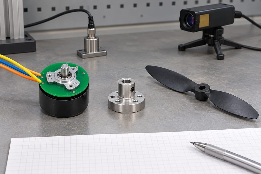
Separate motor, adapter and propeller checks help locate the source of vibration. The parts shown illustrate that staged comparison; powered measurements require the approved mounting, load and guarding arrangement.
After establishing the bare-motor response, install the approved adapter and repeat the measurements at comparable operating speeds. Verify adapter seating before each powered run.
A change following adapter installation may indicate added imbalance, eccentric mounting, or altered dynamics. That change alone cannot identify whether added imbalance, mounting eccentricity, or altered assembly dynamics is responsible.
Next, install the propeller under its approved assembly procedure. Propeller operation introduces aerodynamic forces and may require a different test facility or fixture arrangement.
Maintain the same measurement locations and reference conventions wherever practical. Record fixture changes explicitly when safety or propeller clearance requires a different arrangement.
- Stage 1: Run the bare motor and document its vibration baseline, rotational phase, electrical conditions, and repeatability at approved operating speeds.
- Stage 2: Install the adapter, verify seating and retention, then repeat measurements to identify changes associated with the additional rotating interface.
- Stage 3: Install the propeller and measure the complete assembly under guarded conditions, documenting aerodynamic loading and electrical operating differences.
The three configurations should use matched RPM where practical, but matched speed does not imply identical mechanical loading or identical vibration transmission.
An unloaded motor may draw substantially different current from a motor driving a propeller. The resulting thermal and electromagnetic conditions can affect measured vibration.
| Test Stage | Installed Components | Required Measurements | Controlled Conditions | Interpretation Limitations |
| Bare-motor baseline | Motor without removable adapter or propeller | RPM, vibration amplitude, phase, current, temperature | Fixture, sensor locations, speed, reference | Includes motor and fixture vibration sources |
| Adapter installed | Motor and approved adapter | Previous measurements plus adapter seating and runout | Same instrumentation and approved assembly procedure | Additional vibration may involve alignment or changed dynamics |
| Propeller installed | Motor, adapter, and propeller | Previous measurements plus applicable thrust or loading data | Guarded operation, consistent references, documented loading | Aerodynamic forces and structural response may differ |
| Repeated measurements | Each relevant approved configuration | Amplitude variation, phase variation, operating stability | Repeatable installation and acquisition settings | Measurement variability can obscure small differences |
Record the sequence of runs and component configuration for every dataset. Measurements without reliable configuration identification cannot support a defensible component-level diagnosis.
How Should You Interpret Vibration Results and Operating-Condition Effects?
The measured vibration is the combined response to rotating forces, electromagnetic excitation, aerodynamic loading, and the mechanical characteristics of the mounted assembly.
Separating these effects requires frequency information, synchronous phase measurements, and an understanding of how the supporting structure responds under different operating conditions.
Distinguish Rotational Imbalance from Aerodynamic Excitation
Rotating mass imbalance commonly generates vibration at the fundamental rotational frequency, called the 1× component. This frequency equals shaft rotational speed in RPM divided by sixty.
For example, at an illustrative 6,000 RPM, the fundamental rotational frequency is 100 Hz. The frequency establishes an excitation relationship but not its physical source.
Both rotor-bell imbalance and propeller imbalance can produce 1× vibration because both rotate with the motor shaft under normal mechanical coupling.
Aerodynamic excitation may occur at blade-pass frequency, calculated as rotational frequency multiplied by blade count. A two-blade propeller at 6,000 RPM has a 200 Hz blade-pass frequency.
Blade asymmetry can also produce 1× aerodynamic forces. Therefore, distinguishing blade-pass components from rotational components helps classification but cannot independently identify mass imbalance.
Motor electromagnetic forces, bearing-related excitation, and structural resonance may introduce additional spectral components. Engineers should examine frequency patterns alongside mechanical inspection findings.
Static imbalance creates a resultant centrifugal force, while couple imbalance produces a rotating moment associated with mass distribution across different axial planes.
A propeller that passes a static balancing check may still exhibit dynamic or couple imbalance. Static balance alone cannot demonstrate acceptable vibration during actual operation.
Measurements at multiple stationary locations or directions can help reveal differences in structural response. However, sensor patterns must be interpreted using the actual support geometry.
Compare Vibration Amplitude and Phase Correctly
Vibration amplitude indicates response magnitude, while phase describes its angular relationship to a consistent rotational reference. Together, these quantities support synchronous vector analysis.
Two rotating imbalance sources can reinforce or partially cancel each other. Their combined vibration amplitude therefore depends on both magnitude and relative phase.
Suppose two synchronous vibration responses have equal amplitudes but opposite phases. Their measured resultant may be small despite both individual contributions being significant.
Consequently, subtracting the bare-motor vibration amplitude from the assembled vibration amplitude does not directly calculate the propeller’s imbalance contribution.
For complex vibration quantities, a conceptual comparison is expressed as assembled response minus baseline response. This operation must retain both magnitude and phase information.
However, meaningful vector subtraction requires a common phase reference and a sufficiently unchanged vibration transfer function between the compared configurations.
The transfer function describes how an excitation force produces a measured response through the motor, bearings, mounting fixture, and connected structural components.
Installing the propeller can change bearing forces, structural stiffness, damping, and operating temperature. Such changes may invalidate direct subtraction even with excellent phase synchronization.
Under unsuitable comparison conditions, the calculated vector difference represents a change in measured response, not an isolated measurement of propeller imbalance.
Even under sufficiently stable transfer conditions, a residual response does not directly specify imbalance mass or correction location without a validated balancing model.
Engineers should therefore verify measurement repeatability, structural consistency, and operating conditions before using phase-based differences to support component attribution.
Account for Loading, Resonance, and Measurement Errors
Matched RPM controls rotational frequency but not the complete operating state. Propeller thrust introduces axial loading that may alter bearing position and structural response.
Aerodynamic torque changes motor current and potentially winding temperature. Thermal expansion and bearing clearance variations can influence the measured vibration during longer operating intervals.
A structural resonance may amplify relatively small excitation forces near a particular frequency. Adding a propeller can also change assembly dynamics and resonant behavior.
Where approved, controlled measurements across several operating speeds can help distinguish persistent synchronous excitation from vibration amplified within a narrow resonance region.
Sensor calibration, attachment rigidity, measurement bandwidth, and phase-reference reliability should remain documented. Changes in these factors can resemble genuine mechanical differences.
Background vibration and run-to-run variation also matter. Small differences near the measurement uncertainty should not be presented as confirmed evidence of component imbalance.
Compare temperature and electrical current alongside vibration results. If these operating conditions differ substantially, identify the comparison as conditional rather than mechanically equivalent.
Can Approved Remounting and Propeller Clocking Help Identify the Source?
Repeatable installation provides additional diagnostic evidence. Changing assembly interfaces under controlled conditions can reveal whether vibration depends on component seating or angular orientation.
These checks must follow the approved mechanical design. Arbitrary repositioning or modification can compromise retention, invalidate measurements, or create unacceptable operating hazards.
Evaluate Vibration Consistency After Reinstallation
First, repeat measurements without disturbing the assembly. This establishes the variation associated with the motor, fixture, instrumentation, and operating process.
Next, where permitted, remove and reinstall the adapter or propeller using the specified locating surfaces, fastening method, and tightening requirements.
Measure the assembly again with the same phase convention and comparable operating conditions. Document whether the mounting procedure changes runout, amplitude, or phase.
If vibration changes considerably between nominally identical installations, investigate locating clearance, uneven seating, surface contamination, and fastener retention before assigning a mass-imbalance cause.
Repeatability testing should distinguish measurement scatter from genuine installation sensitivity. A single installation producing low vibration is insufficient to confirm that the original source has been identified and corrected.
Where disassembly affects the angular relationship between components, record their approved reference positions so subsequent measurements remain interpretable.
Compare Propeller Orientation Where Permitted
Some mounting interfaces permit a propeller to occupy different angular positions relative to the shaft. Others have keyed, indexed, or otherwise restricted orientation requirements.
Propeller clocking should be considered only when the actual interface explicitly allows repositioning and the relevant engineering procedure approves such testing.
Where allowed, compare synchronous amplitude and phase after approved orientation changes. Document the angular relationship, remounting procedure, and resulting measurement conditions.
A repeatable orientation-dependent response may indicate interaction between rotating contributors. It does not independently prove the magnitude or location of either component’s imbalance.
Aerodynamic loading, mounting eccentricity, and changes in structural response can complicate this interpretation. Multiple consistent measurements are necessary before drawing a component-level inference.
Do not attach improvised balancing weights or adhesive tape, drill the rotor bell, or alter rotating components without an approved engineering design and qualified procedure.
Likewise, never operate an exposed propeller simply to obtain more convenient sensor access. Guards, remote measurement arrangements, and controlled exclusion zones remain essential.
When permitted remounting cannot distinguish the causes reliably, preserve the evidence and request further component-level evaluation rather than attempting an unsupported field correction.
How Should Engineers Verify the Diagnosis and Approve Corrective Actions?
A reliable diagnosis combines mechanical inspection, staged vibration data, phase relationships, and repeatability evidence. No single vibration amplitude should determine the corrective action.
Verification should identify which findings are confirmed, which mechanisms remain plausible, and which measurements require additional controlled testing before acceptance.
Cross-Check the Evidence Before Assigning a Cause
Begin by comparing the runout inspection with the bare-motor vibration baseline. Confirm whether a suspected defect appears consistently at the expected operating conditions.
Then evaluate changes after adapter installation and complete propeller assembly. Determine whether measured differences exceed repeatability variation and whether structural conditions remain comparable.
A large 1× response from the bare motor may justify investigating the rotor assembly, but it does not eliminate bearing, fixture, or electromagnetic contributions.
Similarly, additional vibration after propeller installation may reflect propeller imbalance, mounting eccentricity, aerodynamic excitation, or changes in the vibration transfer function.
Corrective decisions should follow application-specific requirements and supplier-approved procedures. No single universal vibration or balancing tolerance applies to every outrunner assembly.
| Observed Result | Possible Cause | Verification Method | Interpretation Limitation |
| Elevated bare-motor 1× vibration | Rotor imbalance, runout, bearing or fixture effects | Inspect runout, repeat baseline, evaluate mounting | 1× amplitude does not uniquely identify rotor imbalance |
| Vibration increases after adapter installation | Adapter eccentricity, imbalance, or changed mechanical response | Check adapter runout and approved remount repeatability | Response change is not direct imbalance mass |
| Additional 1× vibration with propeller | Propeller imbalance, mounting error, aerodynamic asymmetry | Compare phase, operating loading, and approved remount tests | Changed transfer function may prevent direct subtraction |
| Strong blade-pass component | Aerodynamic blade interaction or structural excitation | Check frequency relationship, blade condition, and loading | Does not directly quantify mass imbalance |
| Large changes near one speed range | Possible structural resonance | Conduct approved speed-dependent measurements | Response amplification does not establish greater imbalance |
| Variation between repeated installations | Seating, locating clearance, or retention inconsistency | Repeat approved assembly and inspect interfaces | Measurement uncertainty must first be excluded |
This evidence should support a documented cause assessment, including unresolved alternatives. Classification must remain conditional whenever operating or structural differences prevent reliable attribution.
Document Results for Engineering and Supplier Review
For custom brushless DC motor applications, the supplier review should connect measured vibration behavior with the specified rotating assembly, mounting arrangement, and operating duty.
Record the actual component configuration, including motor identification, adapter geometry, propeller interface, and applicable assembly instructions. These details establish the boundary of the diagnosis.
Preserve inspection data showing shaft and rotor-bell runout, adapter alignment, bearing condition, and relevant mounting observations, including the measurement locations and instruments used.
For each powered test, record RPM, synchronous vibration amplitude, phase reference, sensor orientation, electrical current, temperature, and available aerodynamic loading measurements.
Document the fixture arrangement, guarding provisions, operating sequence, stabilization conditions, and repeatability results so another qualified engineer can reproduce the approved procedure.
Include the applicable measurement uncertainty and known comparison limitations. Where the vibration transfer function changes, explain why vector subtraction cannot establish independent imbalance contributions.
Any proposed correction should be reviewed against the rotating assembly’s structural integrity, retention requirements, bearing loading, and intended operating environment before implementation.
Gian Transmission can be provided with the relevant engineering measurements and interface requirements for review without assuming that an unapproved rotor modification is acceptable.
The final engineering handover should contain the following verified records:
- Approved interface drawings: Identify shaft dimensions, rotor-bell interfaces, adapter locating features, propeller mounting geometry, and applicable mechanical retention requirements.
- Inspection and test evidence: Include measured runout, vibration spectra, synchronous amplitude and phase, operating conditions, uncertainty, and documented remounting repeatability.
- Corrective-action decisions: Record confirmed findings, unresolved contributors, authorized actions, responsible approvals, and required follow-up verification for each affected assembly.
- Application-specific acceptance records: Document approved operating conditions, defined acceptance criteria, completed verification results, and authorization for the final motor-propeller configuration.