
Two BLDC motors can deliver equal shaft power at different speeds and torques. A useful 12V versus 24V comparison therefore starts with a clearly defined operating point.
Matched winding designs alter motor constants and phase-current requirements. Applying a higher DC bus voltage to an unchanged winding is a separate case, requiring different controller and thermal checks.
What Does Equal Shaft Power Mean for 12V and 24V BLDC Motors?
Shaft Power, Speed, and Torque
Mechanical output power depends on the torque delivered by the rotating shaft and its angular velocity. Supply voltage alone does not determine either quantity.
For a rotating shaft, the relationship is P_shaft = T × omega, where P_shaft is power in watts, T is torque in N·m, and omega is angular velocity in rad/s.
To convert rotational speed in revolutions per minute into angular velocity, use omega = 2 × pi × rpm / 60. This conversion allows torque and speed requirements to be compared consistently.
Consider an illustrative 60 W shaft load. At 3,000 rpm, the required torque is approximately 0.191 N·m. At 1,500 rpm, it increases to approximately 0.382 N·m.
Both operating points deliver the same mechanical power, but they impose different torque and current demands. Equal shaft power therefore does not establish equivalent electromagnetic loading.
When comparing winding voltage options, engineers should establish whether only output power remains constant or whether shaft speed and torque must also remain unchanged.
Establish a Fair Comparison
A controlled comparison should use identical target speed, torque, duty cycle, motor geometry, and cooling conditions wherever possible. These requirements help isolate winding-related differences.
The mechanical measurement boundary also matters. Motor-shaft power and gearbox-output power are different quantities when transmission losses occur between the two locations.
Electrical input power requires separate consideration because motors with identical shaft output may have different efficiencies. Additional winding or controller losses increase the required input power.
Engineers should also distinguish nominal motor voltage from actual DC bus voltage. A nominal 24V system may experience supply variation during startup, acceleration, and regenerative operation.
For winding comparisons, the most useful reference is a specified mechanical operating point supported by a defined electrical supply range and thermal environment.
How Do DC Bus Current and Phase Current Compare at 12V and 24V?
DC Input Power and Supply Current
At a fixed electrical input power, raising DC supply voltage reduces the average current required from a nearly constant-voltage source. This relationship affects external power distribution.
For an approximately constant bus voltage and stable operating condition, input power can be estimated using P_in = V_bus × I_bus, with voltage in volts and current in amperes.
However, when bus voltage and current fluctuate, true average input power is the time average of their instantaneous product, v_bus(t) × i_bus(t).
With synchronized, uniformly spaced samples, average input power can be approximated by P_in = sum(v_k × i_k) / N over the selected measurement interval.
Multiplying separately averaged voltage and current does not generally produce the correct result when their fluctuations are correlated. Measurement bandwidth and sampling alignment therefore matter.
Consider an illustrative drive delivering 60 W of shaft power at an assumed 80% efficiency from the controller DC input to the shaft. The required DC input power is 75 W.
At a constant 12V supply, the calculated input current is 6.25 A. At a constant 24V supply, it becomes 3.125 A.
These values assume equal efficiency and steady operating conditions. They illustrate the electrical relationship rather than specifying the performance of a particular motor.
Lower DC supply current can reduce cable heating and voltage drop. However, the improvement depends on conductor resistance, actual current waveforms, and the installation.
How Phase Current Relates to Motor Torque
A BLDC motor driver uses electronic switching to regulate the currents supplied to the motor phases from the DC bus. The current flowing through a motor winding is not generally equal to the average current entering the driver.
PWM switching creates intervals of applied voltage and current recirculation. As a result, phase currents may remain substantial even when instantaneous DC supply current is relatively low.
Phase-current requirements depend primarily on the motor torque constant and demanded electromagnetic torque. Bus voltage influences the driver’s ability to establish and regulate those currents.
For a properly controlled unchanged winding, doubling bus voltage does not automatically halve the phase current needed to produce the same shaft torque.
A matched winding redesign can reduce required phase current because its torque constant changes. That effect must be distinguished from the reduction in DC input current.
Engineers should identify whether driver specifications refer to phase RMS current, peak phase current, continuous current, or DC supply current. These measurements are not interchangeable.
Measurement Requirements for Reliable Comparisons
DC power measurements should capture voltage and current simultaneously at a defined electrical boundary. The measurement interval should represent the intended operating condition.
Phase current requires an appropriate measurement method and bandwidth, with RMS values calculated over representative electrical cycles. Peak values should be recorded separately when relevant.
Current definitions also depend on the motor connection and control method. Sinusoidal commutation and six-step commutation can produce different current waveforms under comparable loads.
| Parameter | Measurement Location | Engineering Significance |
| DC bus voltage | Defined controller DC input terminals | Establishes the actual available supply voltage and its variation. |
| Average DC input current | DC supply connection | Shows average supply demand; use true RMS current and transients when checking conductor heating and protection. |
| Average electrical input power | Synchronized bus voltage and current measurements | Supports efficiency calculations using the average instantaneous power. |
| Phase RMS current | Specified motor phase conductors | Supports winding heating calculations and continuous driver-current evaluation. |
| Peak phase current | Motor phase conductors | Supports transient torque and current-limit verification. |
| Motor shaft power | Motor output shaft | Establishes mechanical output for efficiency and equal-load comparisons. |
How Does a Matched 24V Winding Differ from a 12V Winding?
Winding Turns, Back EMF, and Speed Constant
A matched winding redesign changes the electromagnetic relationship between applied voltage, shaft speed, and phase current while retaining the intended mechanical operating point.
Increasing the effective number of series turns raises the back electromotive force generated at a given speed, provided magnetic geometry and flux conditions remain comparable.
Back-EMF constant Ke therefore increases approximately with winding turns under ideal conditions. Speed constant Kv, expressed using a consistent voltage convention, changes inversely.
An illustrative 24V winding may use approximately twice the series turns of its 12V counterpart. Under ideal scaling, Ke doubles while Kv becomes approximately half.
This arrangement allows the redesigned motor to target the same speed with approximately twice the voltage demand. It does not imply that every practical design follows exact proportional scaling.
Actual winding configurations depend on slot geometry, magnetic flux, connection arrangements, conductor placement, and the required speed-torque envelope.
Torque Constant and Required Phase Current
Torque constant Kt relates electromagnetic torque production to current under a specified measurement convention. For comparable magnetic conditions, Kt increases approximately with effective series turns.
Under ideal matched-winding scaling, doubling the winding turns doubles Kt. The current required for a given electromagnetic torque then falls to approximately half.
For illustration, suppose an original winding requires 4 A of phase RMS current at a particular torque, using a defined sinusoidal-control convention.
A matched redesign with twice the torque constant could theoretically produce the same electromagnetic torque at approximately 2 A, assuming equivalent magnetic conditions and control definitions.
Real shaft torque also depends on mechanical losses, current waveform, magnetic saturation, and temperature. These influences must be considered before transferring ideal ratios to hardware.
When specifying custom BLDC motor configurations from Gian Transmission, engineers should identify the required winding constants alongside the intended speed, torque, and control conditions.
Winding Resistance, Inductance, and Copper Fill
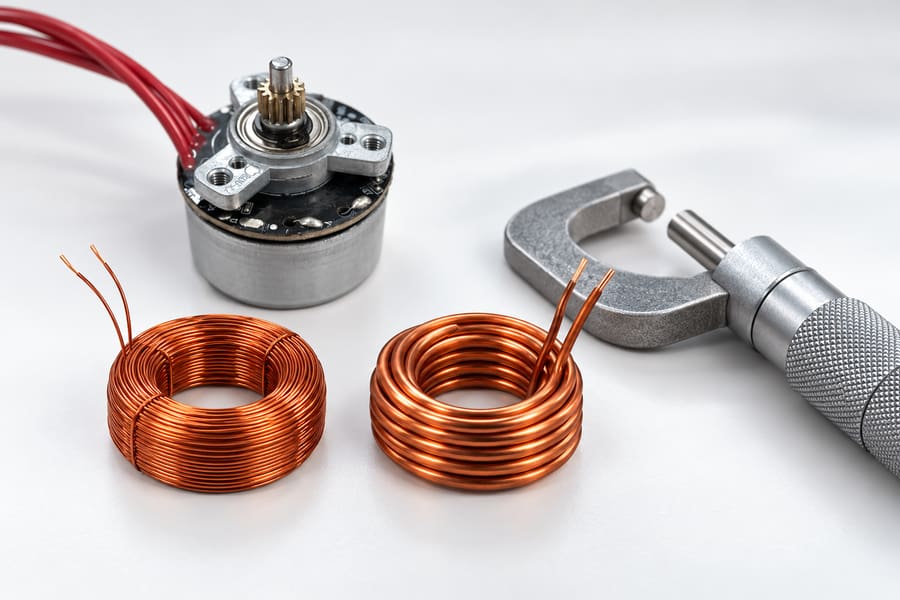
The separate coils illustrate the tradeoff between turns and wire size. They do not represent measured internal windings or a verified voltage conversion of the pictured motor.
Increasing winding turns requires additional conductor length. Within a fixed slot area, accommodating more turns generally requires reducing individual conductor cross-sectional area or changing the winding arrangement.
Under an ideal equal-copper-fill assumption, doubling the turns approximately doubles conductor length while halving conductor cross-sectional area. Under these ideal winding assumptions, the resulting electrical resistance is approximately four times its original value.
Winding resistance can be estimated using R = rho × L / A, with rho representing conductor resistivity, L representing conductor length, and A representing conductor cross-sectional area.
This model assumes comparable mean turn length, conductor material, winding temperature, and effective copper utilization. Practical differences in insulation thickness and end-turn geometry alter the result.
Winding inductance also changes. With unchanged magnetic geometry and approximately linear magnetic conditions, inductance generally scales with the square of the effective turns count.
Doubling turns can therefore produce approximately four times the inductance. Saturation, leakage flux, winding distribution, and mutual coupling can make actual values different.
Resistance influences steady-state voltage drop and copper heating. Inductance influences current ripple and the rate at which current can change under an applied voltage.
Engineers should specify whether resistance and inductance values refer to individual phases or line-to-line terminals. Measurement temperature, frequency, and rotor position may also matter.
Estimating Copper Loss in an Ideally Matched Rewind
Resistive heating in motor windings is determined by their electrical resistance and the RMS current flowing through them. For three identical phases, total copper loss is P_cu = 3 × I_phase_rms² × R_phase.
This expression assumes R_phase represents each complete phase winding at its operating temperature, while I_phase_rms represents the true RMS current in that winding.
Consider an illustrative three-phase, star-connected motor with a phase resistance of 0.20 ohm and phase RMS current of 4 A.
Its calculated copper loss is 3 × 4² × 0.20 = 9.6 W. These assumed values describe a calculation example, not a product specification.
If a matched winding doubles its turns, the ideal resistance becomes 0.80 ohm while required phase RMS current falls to 2 A.
The corresponding loss is 3 × 2² × 0.80 = 9.6 W. Thus, ideal voltage scaling does not inherently reduce winding copper loss.
Practical results can differ because winding resistance changes with temperature, and conductor arrangement, current ripple, copper fill, and magnetic loading may not remain equivalent.
What Happens When an Existing 12V BLDC Winding Is Operated from 24V?
Electrical Parameters Remain Unchanged
Connecting an existing winding to a higher-voltage DC bus does not change its number of turns, magnetic geometry, or fundamental winding constants.
Its Kv, Kt, resistance, and inductance remain approximately unchanged at comparable temperatures and magnetic conditions. The available electrical voltage headroom, however, increases.
At higher rotational speeds, motor back EMF increases. Additional bus voltage may allow the driver to maintain phase-current regulation where a lower-voltage supply would become limiting.
This can extend the attainable speed range under suitable control, but it does not establish that the motor is mechanically or thermally approved for higher-speed operation.
An uncontrolled or incorrectly configured drive may expose the motor to excessive speed or current. Voltage compatibility must therefore include operating limits and protection behavior.
Current Regulation and Operating Limits
A suitable motor driver can regulate phase current using PWM, allowing an unchanged winding to operate at its original speed and torque despite a higher DC bus.
For the same electromagnetic torque and unchanged Kt, the required phase-current level remains approximately the same. The higher bus voltage does not automatically reduce winding heating.
Controller voltage ratings, power-stage components, current sensing, insulation, and protection thresholds must support the actual supply conditions, including transients and regeneration.
Higher bus voltage can also affect current ripple, switching losses, and electromagnetic interference. Controller settings appropriate at 12V may require evaluation before 24V operation.
The available voltage across a winding must overcome back EMF, resistive drop, and inductive voltage demand. The inverter’s modulation capability further limits usable voltage.
These factors determine how quickly current can rise during acceleration or load disturbances. Additional voltage headroom may improve dynamic response when the controller permits it.
Engineers should not assume that a motor labeled for 12V operation can safely use a 24V bus without documented compatibility and representative testing.
How Does This Differ from a Matched Rewind?
A matched 24V rewind changes winding turns, torque constant, back-EMF constant, phase resistance, and inductance to support a different electrical operating arrangement.
An unchanged winding operated from 24V retains its original current-to-torque relationship. The driver instead manages the increased available voltage through its control strategy.
Both configurations might deliver identical shaft power, but their phase-current demands, electrical losses, voltage margins, and controller requirements need not match.
How Do 12V and 24V Windings Affect Losses, Temperature, and Driver Requirements?
Motor Losses and Thermal Behavior
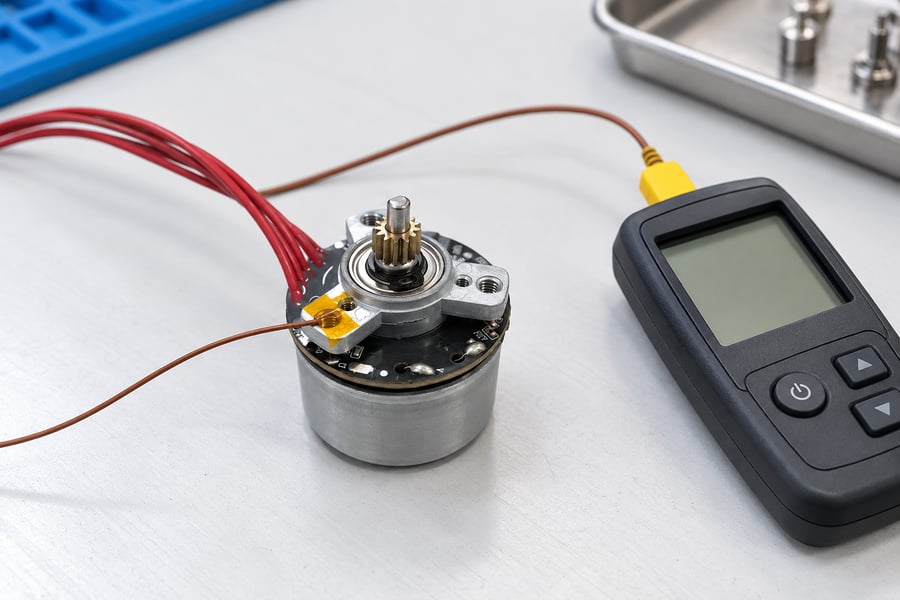
This illustration shows a stationary mounting-point temperature check. Such a reading is a thermal reference; winding hot-spot temperature requires a validated measurement or correlation.
Ideal matched-winding calculations predict approximately unchanged copper loss at equal electromagnetic torque. Actual motor efficiency also depends on magnetic, mechanical, and switching-related effects.
Core losses are influenced by rotational speed, magnetic flux variation, and material characteristics. Their values cannot be determined from nominal winding voltage alone.
PWM-induced current ripple can increase RMS current and introduce additional frequency-dependent losses. Conductor arrangement and control settings influence these effects.
Winding temperature affects resistance because copper resistivity increases as temperature rises. Comparisons should therefore distinguish cold electrical measurements from stabilized operating conditions.
Thermal performance also depends on housing conduction, airflow, mounting interfaces, and operating duration. Two electrically similar windings may develop different temperatures in different installations.
Continuous-load testing should record winding or suitably correlated temperature measurements alongside shaft torque, speed, and current. Acceptance limits must reflect the approved insulation and application requirements.
Driver Voltage and Current Requirements
Motor-driver selection must consider both available DC bus voltage and required motor phase current. These ratings describe different electrical stresses within the system.
For a matched 24V winding, reduced phase-current demand may allow different current-sensing and power-stage choices. However, higher voltage imposes corresponding requirements on switching components.
The controller must tolerate the complete bus voltage range, including supply tolerance, startup disturbances, and voltage increases caused by regenerative energy.
PWM frequency, current-loop tuning, and current-sensing resolution should be evaluated against winding resistance and inductance. Changed winding constants can require different control parameters.
Higher bus voltage may improve available current-response headroom, but it can also increase switching stress or current ripple under certain operating conditions.
Engineers reviewing BLDC motor driver options from Gian Transmission should confirm electrical compatibility with the selected winding and intended control method.
Hall-Sensored and Sensorless Control
Hall-sensored operation uses rotor-position signals to support commutation. The sensor supply, signal levels, wiring arrangement, and electrical isolation requirements must remain compatible with the controller.
Sensorless control commonly relies on electrical measurements and motor-model information. Back-EMF characteristics, winding parameters, speed, and loading can influence estimation performance.
At low speeds, limited back EMF can make rotor-position estimation more challenging. Startup behavior should therefore be verified at the required load and supply conditions.
A winding redesign may change the electrical parameters used by a sensorless algorithm. Controller commissioning should account for those changes rather than reusing settings without verification.
Wiring and Power Distribution
Lower DC supply current can reduce resistive losses in external wiring. For the same conductor resistance, halving current reduces I²R heating to approximately one-quarter.
This benefit applies to the relevant DC distribution path, not automatically to motor phase conductors. Phase-wire heating depends on their actual RMS currents and resistances.
Cable length, connector resistance, supply tolerance, and allowable voltage drop should be reviewed together. A higher-voltage architecture can improve distribution efficiency without changing motor efficiency.
Protection devices and insulation must also be appropriate for the complete system. Lower current alone does not establish compatibility with a higher operating voltage.
How Should Engineers Select and Validate 12V or 24V BLDC Windings?
Match the Winding to the Application
Selection should begin with the required mechanical operating envelope. Engineers need continuous torque, peak torque, shaft speed, acceleration, and duty-cycle information rather than power alone.
A system operating mainly at one steady speed may favor a different winding optimization from an application requiring frequent acceleration and a broad speed range.
Available DC supply voltage also matters. The selected winding must operate across the permitted bus range while maintaining adequate voltage margin at demanding speed-torque combinations.
Motor dimensions, winding space, mounting arrangements, and cooling conditions constrain the design. Higher nominal voltage does not eliminate these mechanical and thermal considerations.
The comparison should include driver requirements, cable losses, connectors, and protection components. A lower-current arrangement may reduce distribution losses while introducing other integration costs.
Verify Performance at Equivalent Operating Points
Testing should reproduce the same mechanical operating points for both winding options. Shaft torque and speed must be measured rather than inferred solely from electrical input.
DC voltage and current should be recorded synchronously so that average instantaneous electrical power can be calculated over the same operating interval.
During transient operation, changes in stored mechanical and electrical energy can affect the measured input-output relationship. Steady-state efficiency should not be inferred from an unmatched acceleration interval.
Where regeneration occurs, returned energy should be identified using a consistent power sign convention. Positive motoring energy and recovered energy may require separate reporting.
Phase RMS current, peak current, winding temperature, and driver temperature should be monitored at representative operating points. These measurements reveal limits hidden by nominal voltage comparisons.
Startup, load disturbances, acceleration, deceleration, and continuous operation should be included where relevant. Testing must remain within supplier-approved electrical and mechanical limits.
| Engineering Requirement | Measurement or Evidence | Acceptance Basis |
| Mechanical output | Measured shaft speed, torque, and calculated power | Required operating points achieved within application-defined tolerances |
| Electrical input | Synchronized DC bus voltage and current records | Input power and efficiency evaluated over matching operating intervals |
| Winding characteristics | Resistance, inductance, Ke, and Kt under documented conditions | Agreement with the approved winding design and measurement conventions |
| Current capability | Phase RMS and peak-current measurements | Compliance with approved motor and driver operating limits |
| Thermal performance | Motor and driver temperature records under representative duty | Application-defined temperature limits maintained |
| Dynamic operation | Startup, acceleration, load-change, and deceleration records | Required response achieved without unacceptable current limiting or loss of control |
| Voltage compatibility | Testing across the specified DC bus operating range | Stable operation and appropriate protection behavior throughout the approved range |
| Control compatibility | Hall-sensored or sensorless operating records | Required startup, commutation, and speed-control performance verified |
What Information Should Engineers Provide to Gian Transmission?
A useful customization request should define the intended shaft speed-torque envelope, duty cycle, available supply voltage range, and the required continuous and transient operating conditions.
The specification should also identify motor dimensions, mounting interfaces, shaft requirements, cooling arrangements, and any restrictions on winding space or external wiring.
Driver information should include allowable phase current, DC bus operating range, commutation method, current-control requirements, and the preferred Hall-sensored or sensorless arrangement.
Requested electrical data should identify winding resistance, inductance, back-EMF constant, torque constant, and their measurement conditions. Phase and line-to-line conventions must be explicit.
Acceptance requirements should distinguish matched-winding performance from unchanged-winding higher-voltage compatibility. Each case needs appropriate electrical limits, operating conditions, and verification procedures.
Final engineering approval should be supported by controlled winding drawings, electrical parameter records, approved driver settings, measured speed-torque performance, synchronized power data, thermal test results, and documented acceptance decisions.