
A sensorless inrunner motor should restart a spinning pump by detecting actual rotor movement, identifying direction and electrical phase when observable, then synchronizing inverter output before applying limited torque.
Unlike a stationary start, this process must accommodate weak back EMF, hydraulic backflow, pressure transients, regenerated DC-bus energy, and power recovery. Flying-start capability requires controller support and application validation.
Why Is Restarting a Spinning Pump Different from Starting at Rest?
A pump does not necessarily stop rotating when its motor drive is disabled. The rotor, impeller, and moving liquid can retain enough energy to maintain rotation after electrical torque disappears.
What Happens When a Pump Keeps Spinning After Shutdown?
During normal coast-down, mechanical friction and hydraulic resistance gradually reduce rotational speed. However, pressure differences across the pump may continue driving the impeller or reverse its direction.
The motor controller may therefore encounter a rotor moving at an unknown speed and electrical angle. Its previous speed command cannot establish the actual rotor position after an interruption.
Applying inverter output without accounting for existing rotation can produce substantial current transients. Depending on the phase relationship, the motor may accelerate, brake, or briefly generate energy unexpectedly.
How Does Flying Start Differ from a Stationary Startup?
A conventional sensorless startup may use rotor alignment followed by controlled open-loop acceleration. This approach assumes the rotor is stationary or that its initial movement is otherwise managed.
Flying start, also called catch-on-the-fly, instead attempts to identify existing motion and synchronize the inverter before establishing normal motoring torque.
Stationary alignment pulses must not be applied blindly while a pump is spinning. They may produce opposing torque, disturb hydraulic flow, or create excessive electrical current.
Importantly, sensorless operation does not automatically mean flying-start capability. The controller must specifically support spinning-rotor detection, synchronization, and appropriate recovery when detection fails.
How Can a Sensorless Drive Detect Rotor Motion Before Restarting?
A sensorless drive estimates rotor position without relying on a dedicated mechanical position sensor. For spinning-restart applications, the quality of this estimate determines whether torque can be applied predictably.
How Does Back EMF Reveal Rotor Direction and Speed?
As the permanent-magnet rotor turns, changing magnetic flux induces back electromotive force in the stationary stator windings through electromagnetic induction within the motor. Its electrical characteristics contain information about rotor speed and magnetic position.
With suitable measurement hardware, a controller can observe phase-voltage relationships or use an estimator to infer direction, electrical speed, and rotor electrical phase.
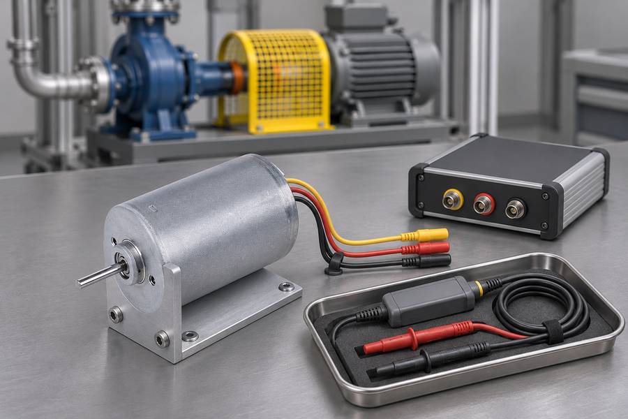
Mechanical speed and electrical frequency are related through the number of rotor pole pairs. The estimator must use the correct motor configuration to interpret measured electrical movement.
Reliable detection also depends on the inverter’s measurement arrangement. Terminal voltages, switching states, filtering, and available observation intervals affect what information the controller can obtain.
Why Is Rotor Detection Difficult at Low Speed?
Back-EMF amplitude generally decreases as rotational speed falls. At sufficiently low speeds, the useful signal may become difficult to distinguish from measurement noise and estimation errors.
Electrical resistance, inductance, temperature, and filtering can influence estimation accuracy. These effects become especially important when the available signal is weak or changing rapidly.
An unreliable speed estimate must not be interpreted as confirmed standstill. A slowly rotating pump may still have enough mechanical movement to make stationary alignment inappropriate.
There is no universal minimum speed at which sensorless flying start becomes reliable. The usable detection range depends on the motor, inverter, algorithm, and operating conditions.
How Do Six-Step and FOC Sensorless Controllers Differ?
Six-step commutation and field-oriented control both require rotor information, but they use that information differently during synchronization and subsequent torque production.
- Six-step commutation: The controller must identify an appropriate commutation sector, direction, and timing before establishing controlled torque. Back-EMF zero-crossing techniques require suitable electrical observation conditions.
- Field-oriented control: The controller needs a sufficiently accurate electrical-angle estimate to align its current-control reference frame with the rotating magnetic field.
- Observer initialization: Estimation methods must establish a usable rotor state before normal closed-loop control can resume. Their behavior depends on the implemented algorithm.
- Capture capability: Neither six-step nor FOC operation guarantees flying-start support without an appropriate controller strategy and validated hardware.
The wider brushless DC motor category includes different motor and controller arrangements. Engineers must therefore verify the actual commutation architecture rather than assume identical restart behavior.
What Is the Correct Flying-Start Sequence for a Spinning Pump?
A suitable restart sequence separates permission checks, rotor-state detection, electrical synchronization, and torque recovery. Combining these actions without defined conditions makes unexpected motor behavior harder to prevent.
Step 1 – Confirm Restart Permission and Drive Readiness
Before attempting rotor capture, the controller must establish that electrical power, protective conditions, and the hydraulic process permit a restart.
DC-bus voltage, inverter readiness, current sensing, and relevant drive faults should be checked. Hydraulic pressure and valve conditions may also determine whether restarting is acceptable.
Restored power alone should not create an automatic torque command. The restart logic must distinguish an authorized process request from recovery after a protective shutdown.
Step 2 – Establish the Actual Rotor State
When restart is permitted, the controller should determine whether the rotor is moving forward, backward, or at a speed where reliable detection is unavailable.
For back-EMF-based capture, the drive obtains direction, electrical speed, and phase information when the signal is sufficiently observable. Estimates must remain consistent before synchronization proceeds.
The controller should not substitute the last commanded speed for measured or estimated movement. Hydraulic backflow can create a rotor direction entirely different from the previous command.
If direction or electrical phase cannot be established confidently, torque pickup must not proceed through an assumed flying-start state. The controller needs a defined fallback.
Step 3 – Synchronize the Inverter with the Spinning Motor
Once rotor motion is known, the inverter must establish an electrical output state compatible with the motor’s existing rotation before developing significant torque.
Synchronization involves coordinating electrical frequency, phase, and the effective applied voltage relative to back EMF. The precise implementation depends on the controller architecture.
In FOC operation, an incorrect angle estimate can misdirect current between torque-producing and other components. In six-step operation, incorrect commutation timing can create similar disturbances.
Synchronization should therefore be verified through appropriate electrical feedback. A speed estimate alone does not demonstrate that the inverter is ready for controlled torque production.
Step 4 – Apply Current-Limited Torque and Recover Speed
After synchronization, the controller can introduce torque under defined current limits. The transition should avoid abrupt acceleration or braking while the hydraulic system remains active.
Pump inertia affects how quickly speed can change under available torque. Hydraulic pressure and flow conditions may impose additional restrictions beyond the motor’s electrical capability.
The torque command should transition toward the required operating point only while current, voltage, and rotor estimation remain acceptable. A current limit alone cannot guarantee hydraulic safety.
Step 5 – Verify Stable Operation
Successful capture requires more than a temporary increase in rotational speed. The controller must maintain suitable commutation or electrical-angle estimation while the pump approaches its requested operating condition.
Monitor measured motor current, DC-bus voltage, estimated speed, and relevant hydraulic signals. Unexpected current oscillation, unstable speed estimation, or abnormal pressure changes require investigation.
When synchronization is lost, the drive should enter a validated protective response. The selected response must consider whether coasting, torque removal, or controlled deceleration is hydraulically acceptable.
What Should Happen If the Rotor State Cannot Be Detected Reliably?
Weak back EMF creates a critical decision point during flying start. The drive may know that a restart was requested without having sufficient information to synchronize safely.
Recognizing Weak or Unreliable Speed Feedback
Near standstill, voltage measurements may provide insufficient information for a dependable electrical-angle estimate. Rapidly changing speed or electrical interference can also reduce estimation confidence.
The controller should distinguish a confirmed stationary condition from an unknown rotor state. These conditions require different startup decisions even when the measured back EMF appears small.
Acceptance criteria for signal quality and estimation stability must be established for the actual drive and motor. A universal voltage or rotational-speed threshold would be misleading.
Selecting a Safe Fallback Restart Method
When spinning capture is unavailable, the controller may continue observing rotor motion, permit coast-down, or use another validated detection method supported by its hardware.
A conventional stationary startup becomes appropriate only when the required standstill conditions have been established and the hydraulic system permits that startup sequence.
Waiting for a fixed period does not necessarily prove that the pump stopped. Pressure-driven backflow may sustain rotation or cause reversal after an apparently normal coast-down interval.
| Rotor condition | Possible restart response | Primary concern |
| Forward rotation with reliable estimate | Synchronize and apply limited torque | Current and torque transients |
| Low-speed rotation with uncertain estimate | Continue observation or use validated fallback | Unreliable electrical phase |
| Confirmed standstill | Use approved stationary startup | Starting load and hydraulic conditions |
| Reverse rotation | Evaluate hydraulic state before recovery | Opposing torque and pressure disturbances |
| Unknown direction or unstable estimate | Inhibit torque until the condition is resolved | Uncontrolled motor response |
| Synchronization lost during restart | Execute validated protective response | Unexpected braking or excessive current |
These responses represent engineering options rather than a universal control algorithm. Each transition requires defined permission conditions and verification against the actual installation.
How Do Reverse Flow and Hydraulic Conditions Affect a Spinning-Pump Restart?
Electrical synchronization cannot be evaluated independently of the pump’s hydraulic condition. A motor may be electrically capable of producing torque while the connected fluid system makes that action unsuitable.
Why Can a Pump Rotate Backward After Shutdown?
When pressure on the discharge side exceeds the opposing hydraulic resistance, fluid may flow backward through the pump and drive its impeller in reverse.
Check valves can influence this behavior, but their actual closing characteristics and installation must be considered. A valve’s presence does not establish that reverse rotation is impossible.
Piping arrangement, static head, trapped pressure, and downstream equipment affect the direction and duration of hydraulic movement. These conditions may change between operating states.
How Do Pump Inertia and Pressure Conditions Affect Torque Recovery?
Rotor and impeller inertia determine part of the torque required to change speed. Moving liquid adds hydraulic effects that depend on flow resistance and system configuration.
An abrupt speed change can generate pressure transients, particularly when valves or flow restrictions limit how quickly the liquid can respond.
Suction pressure, priming condition, and available liquid supply also affect acceptable operation. Restarting into unsuitable conditions may create cavitation or inadequate flow.
Engineers should evaluate the motor’s proposed acceleration profile against the pump’s operating envelope. An electrically smooth restart is not necessarily a hydraulically acceptable restart.
What Should the Drive Do When Reverse Rotation Is Detected?
Reverse rotation requires an explicitly approved response. Immediately applying forward torque creates opposition between the motor’s electromagnetic torque and the existing hydraulic motion.
This interaction can produce mechanical stress and pressure disturbances. Electrical braking may also return energy to the DC bus, introducing an additional limitation.
- Coast-down: Permit rotation to decay only when the hydraulic system can safely accommodate the resulting flow and pressure behavior.
- Hydraulic intervention: Coordinate approved valve or isolation operations where the installation provides suitable equipment and control logic.
- Controlled deceleration: Consider active braking only after evaluating torque, pressure transients, and the available regenerative-energy path.
- Restart inhibition: Prevent forward acceleration when the detected condition cannot be handled through a validated recovery sequence.
Reverse rotation should never be treated as a simple direction-command error. The hydraulic source of rotation may continue acting even after the controller attempts to oppose it.
How Do Regenerative Energy and Power Interruptions Affect Restart Safety?
A spinning permanent-magnet motor can generate electrical energy independently of a commanded motoring state. The inverter and DC-bus arrangement determine how that energy interacts with the drive.
Why Can a Spinning Motor Return Energy to the DC Bus?
When electromagnetic torque opposes rotor motion, mechanical energy can be converted into electrical energy. Controlled deceleration and externally driven rotation are common situations requiring evaluation.
Regenerated energy can raise DC-bus voltage if the connected system cannot absorb, return, or dissipate it appropriately. Excessive bus voltage may trigger protective shutdowns or damage inadequately protected equipment.
A spinning motor does not necessarily charge the DC bus under every condition. The actual energy path depends on back-EMF magnitude, bus voltage, inverter topology, and switching state.
Engineers must distinguish deliberate regenerative braking from unintended energy flow during synchronization. Both require attention, but their control mechanisms and operating conditions can differ.
What Happens When Drive Power Is Lost and Restored?
A pump may continue rotating while its inverter output is disabled or its control electronics are unavailable. The rotor state at power restoration can differ substantially from its previous state.
Motor-output disablement, control-power interruption, and complete supply loss are not equivalent events. Each can leave different measurement, protection, and restart functions available.
Depending on inverter hardware and electrical conditions, a rotating motor may influence the DC bus through existing circuit paths even when normal switching commands are absent.
After power returns, the controller must reestablish measurement validity, operating permissions, and rotor-state information. Retaining an earlier rotor-angle estimate without verification is inappropriate.
How Should Regenerative and DC-Bus Limits Be Managed?
The electrical design must establish how regenerated energy is handled during deceleration, reverse-spin recovery, and unexpected hydraulic driving conditions.
Not every drive can return energy to its supply or dissipate substantial regenerative power. Such functions must be verified rather than assumed from the motor type.
- Bus-voltage supervision: Confirm that voltage remains within the approved operating range throughout capture and torque recovery.
- Current limitation: Apply appropriate motor and inverter current restrictions during synchronization and regenerative operation.
- Energy handling: Verify any required dissipation or energy-return equipment against the expected operating conditions.
- Fault response: Define protective behavior for excessive bus voltage, insufficient supply voltage, and unstable electrical synchronization.
Forced braking must not be introduced solely to simplify rotor detection. Its acceptability depends on the electrical energy path and the pump’s hydraulic response.
Which Interlocks and Protection Functions Are Needed for Safe Restart?
Restart authorization should combine electrical readiness with process conditions and any required safety-related permissions. A valid rotor estimate does not override an active protective condition.
Electrical and Motor Protection Conditions
Drive readiness includes acceptable DC-bus voltage, valid current measurements, suitable temperature conditions, and the absence of faults that prohibit torque production.
Speed and direction limits must also correspond to the actual installation. These limits may differ between normal pumping, permitted coast-down, and approved recovery operations.
Loss of synchronization requires a defined response, including conditions for torque inhibition and subsequent restart authorization. Repeated automatic attempts should not be assumed acceptable.
Hydraulic and Process Interlocks
Relevant process checks may include suction pressure, discharge pressure, valve position, priming status, and liquid availability. Required signals depend on the pump and installation.
A controller should not accelerate the motor simply because its electrical state is acceptable. The hydraulic process must also permit the intended direction and speed change.
Ordinary process sensors must not be treated as safety-rated protective devices without appropriate design and validation. Their use for operation monitoring does not establish safety integrity.
Automatic Restart Permissions and Fault Recovery
Automatic recovery permissions should distinguish ordinary operating interruptions from emergency stops, protective trips, and faults requiring inspection or deliberate operator action.
Resetting a protective function must not itself cause an unintended start. Restart commands require separate authorization consistent with the system’s risk assessment.
Stored hydraulic pressure, moving fluid, rotor inertia, and electrical energy should be included in the risk assessment because hazardous movement may continue after torque is removed.
How Should a Sensorless Spinning-Pump Restart Be Validated?
Flying-start validation must demonstrate both reliable motor capture and acceptable hydraulic behavior. Testing only whether the motor reaches commanded speed overlooks potentially damaging transients.
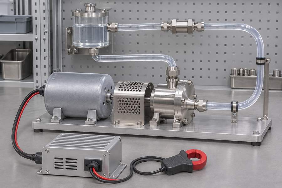
Testing Different Rotor Rotation Conditions
Tests should cover representative forward rotation, near-zero-speed uncertainty, and reverse rotation when backflow is possible. The selected conditions must reflect the installation’s expected operating envelope.
Reliable rotor detection should be verified independently where practical. An independent speed or position reference during development can expose errors hidden by the controller’s own estimates.
Capture should not be declared successful merely because the pump accelerates. Electrical synchronization, current behavior, and mechanical response must remain acceptable throughout the transition.
Evaluating Electrical and Hydraulic Restart Behavior
Record motor current, DC-bus voltage, estimated speed, and relevant controller states during each restart. Include suitable pressure and flow measurements for hydraulic evaluation.
Compare transient behavior with application-specific acceptance limits. Current peaks, voltage excursions, unstable estimates, and unusual pressure changes warrant examination before approving restart logic.
When direct shaft-torque measurement is unavailable, electrical current alone should not be treated as complete proof of mechanical loading. Appropriate supporting measurements and engineering analysis remain necessary.
Validating Power-Loss and Fault-Recovery Conditions
Power-interruption tests should distinguish brief supply disturbances from interruptions that reset the controller. Each scenario may require different initialization and restart permissions.
Validation should include failed rotor detection, synchronization loss, voltage faults, and interrupted recovery sequences. The protective response is as important as successful capture.
| Test condition | Key observations | Acceptance focus |
| Forward rotation at low speed | Back EMF, estimated electrical angle and speed | Reliable detection or safe fallback |
| Forward rotation at higher speed | Current, synchronization, torque transition | Controlled capture without unacceptable transients |
| Reverse rotation due to backflow | Direction estimate, pressure, torque response | Approved reverse-spin handling |
| Near-zero-speed uncertainty | Estimator confidence, fallback transition | No inappropriate stationary alignment |
| Short supply interruption | Rotor-state recovery, DC-bus voltage | Correct restart authorization |
| Extended power interruption | Controller reset, coast-down, bus recovery | Safe startup-state determination |
| Restrictive hydraulic condition | Pressure, flow, acceleration response | Hydraulic operating limits respected |
| Synchronization failure | Current, bus voltage, protective response | Controlled fault handling |
The validation matrix identifies conditions requiring investigation, not universal pass criteria. Acceptable limits must come from the selected motor, controller, pump, and hydraulic design.
Repeat representative tests under relevant temperature, supply-voltage, and loading conditions. A single successful capture does not establish dependable operation throughout the intended application range.
What Should Engineers Verify When Selecting a Sensorless Inrunner Motor for a Pump?
Motor selection should begin with the pump’s mechanical and electrical requirements. Flying-start behavior must then be evaluated as a separate motor-drive-system function.
Motor Electrical and Mechanical Requirements
Winding characteristics, resistance, inductance, back-EMF behavior, and pole-pair count influence controller compatibility. The drive must use appropriate motor data for its chosen estimation method.
Engineers should also examine operating voltage, permitted current, speed range, temperature, and duty cycle. These requirements affect both normal operation and the available restart operating envelope.
Mechanical checks include shaft configuration, coupling geometry, bearing loading, mounting accuracy, and installation constraints. Pump-driven forces may remain present even when motor torque is disabled.
Gian Transmission provides customization options for inrunner brushless DC motors, including application-specific electrical and mechanical interfaces. These options can support integration with pump assemblies and compatible drives.
However, customized motor interfaces do not establish a model-specific flying-start guarantee. Restart performance depends on the complete electrical control and hydraulic arrangement.
Controller Capabilities That Must Be Verified Separately
The selected drive must explicitly support the required spinning-restart behavior. A specification stating sensorless control is insufficient evidence of catch-on-the-fly capability.
- Rotor detection: Verify forward and reverse motion detection over the application’s relevant operating conditions.
- Synchronization: Confirm that the chosen six-step or FOC method can establish a suitable commutation state before torque pickup.
- Current control: Check the availability of controlled torque recovery and applicable current limits.
- Low-speed fallback: Establish how the controller handles uncertain rotor position without blindly initiating stationary alignment.
- Regenerative protection: Verify DC-bus supervision and the available energy-handling arrangement.
- Recovery logic: Confirm fault handling, power-restoration permissions, and compatibility with required interlocks.
Application Information Needed Before Motor and Drive Integration
A meaningful restart assessment requires more than rated motor speed and voltage. The engineering record should describe how the pump behaves when torque disappears.
Record the pump type, rotor and impeller inertia, intended operating range, duty cycle, and relevant coupled mechanical components. Include available hydraulic operating information.
Document suction and discharge conditions, possible reverse flow, check-valve behavior, and permitted restart states. Identify whether external pressure can continue driving the impeller.
Electrical documentation should identify the drive architecture, motor parameters, supply arrangement, sensing provisions, and expected interruption conditions. These details establish the boundaries for controller evaluation.
Final Engineering Checks and Restart Acceptance Records
Before authorizing automatic flying start, engineering personnel should maintain a controlled acceptance record linking each required restart condition to its verification method.
- Motor identification: Record approved motor specifications, winding data, pole-pair count, and mechanical interface drawings.
- Controller configuration: Record the selected control method, verified flying-start functions, current limits, and approved recovery settings.
- Detection acceptance: Document the conditions under which rotor direction, speed, and electrical phase estimates are considered reliable.
- Hydraulic boundaries: Record permissible pressure, flow, valve states, reverse-rotation conditions, and acceleration restrictions.
- Electrical protection: Document DC-bus operating limits, available regenerative-energy handling, and associated fault responses.
- Restart permissions: Identify required interlocks, permitted automatic-recovery events, and faults requiring deliberate operator authorization.
- Validation evidence: Retain measured current, bus-voltage, rotor-state, and hydraulic-response records from representative restart conditions.
- Approval status: Identify unresolved conditions, corrective actions, responsible reviewers, and the authorized motor-drive-pump configuration.
Acceptance should be granted only for the documented configuration and verified operating envelope. Changes to motor windings, controller firmware, hydraulic components, or restart logic require an assessment of their effect on previously accepted behavior.