
A custom BLDC motor may meet performance requirements while carrying winding insulation risks. Buyers need evidence that its insulation barriers suit the electrical, thermal, and mechanical stresses of the application.
These seven checks cover construction records, workmanship, electrical screening, PWM compatibility, and endurance evidence. They distinguish what each test can prove and establish supplier questions for approval.
Is the Winding Insulation System and Thermal Class Documented?
Winding insulation protects different electrical boundaries. Groundwall insulation separates energized conductors from grounded motor structures, phase-to-phase insulation separates winding circuits, and interturn insulation protects adjacent conductor turns.
These boundaries require different verification methods. Insulation resistance evaluates leakage, dielectric withstand tests electrical strength across specified barriers, and interturn verification addresses localized weaknesses between turns.
For a custom design, buyers should agree on insulation requirements, test procedures, acceptance criteria, and required records before ordering production units.
The first procurement check concerns the complete insulation system rather than a single insulating material. A winding contains multiple components that must function together throughout operation.
The chosen insulation materials influence electrical separation, thermal durability, manufacturing consistency, and the winding’s ability to withstand mechanical damage. Each material should suit its location and the surrounding components.
What Insulation Materials and Construction Details Should Be Specified?
Request documentation identifying magnet-wire coating, slot liners, phase separators, insulating sleeves, lead insulation, and any impregnation materials included in the proposed winding construction.
Material specifications should identify applicable grades, relevant thicknesses, construction details, and controlled substitutions. A generic material description may not establish whether a replacement preserves the approved insulation arrangement.
For a custom brushless DC motor, electrical and mechanical customization should be reviewed together because winding dimensions, slot geometry, and lead routing affect insulation requirements.
- Magnet-wire insulation: Identify the conductor coating and its suitability for the intended winding and operating conditions.
- Slot insulation: Document insulating barriers separating the winding from stator laminations, including critical placement and overlap requirements.
- Phase separation: Define barriers between different winding phases wherever the construction requires additional electrical separation.
- Lead protection: Specify sleeves, terminal insulation, strain relief, and protection against contact with metal edges.
- Impregnation system: Identify materials and processing requirements that support insulation stability and winding restraint.
Buyers should also request the approved winding drawing revision. This establishes which insulation components belong to the design and supports comparison with later production records.
How Should the Insulation Thermal Class Be Evaluated?
An insulation thermal class describes a temperature-related classification of the insulation system. It does not automatically define the permissible temperature rise of every assembled motor.
The engineering review should consider expected winding hot spots, surrounding temperature, cooling conditions, duty cycle, and the temperature capability of adjacent components.
Temperature measured at the motor housing may differ substantially from the hottest winding location. The supplier should explain how winding temperature estimates or measurements support the proposed operating limits.
Request the technical basis for the declared thermal classification without assuming a particular certification, qualification program, or standardized test capability exists.
If insulation materials or winding processes change, determine whether their compatibility and thermal suitability require renewed engineering evaluation before the revised construction enters production.
Are Physical Insulation Barriers and Winding Workmanship Properly Controlled?
Even appropriately selected insulation materials can fail when manufacturing damages their protective surfaces. Physical inspection therefore provides information that electrical screening alone may not reveal.
Winding operations involve conductor tension, bending, insertion, routing, and assembly handling. Each operation can introduce localized mechanical stress into insulating coatings or barriers.
Which Winding Locations Are Most Vulnerable to Insulation Damage?
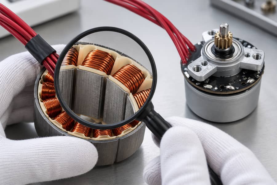
A representative stator sample illustrates liner placement and enamel inspection beside the finished motor. Its winding geometry is illustrative and does not specify the internal construction of this product.
Slot openings and lamination edges deserve particular attention because conductors may contact metal surfaces during winding insertion, forming, or subsequent assembly operations.
End windings and crossover regions require suitable separation and mechanical support. Unsupported conductors can move during operation, creating abrasion or stressing insulation at contact points.
Lead exits present another vulnerable area. Changes in conductor direction, solder joints, terminal connections, and cable movement can concentrate mechanical loads near insulation transitions.
- Slot openings: Check for damaged liners, exposed sharp edges, and displaced insulating barriers.
- End windings: Inspect conductor routing, phase separation, crossing points, and mechanical restraint.
- Lead exits: Verify sleeve coverage, strain relief, clearance from metal components, and protection during assembly.
- Winding surfaces: Look for visible coating damage, trapped debris, distorted conductors, or evidence of excessive handling force.
Impregnation can help stabilize windings when appropriately specified and applied. However, impregnation should not be treated as a universal substitute for necessary physical insulation barriers.
Where the construction uses insulating sleeves or phase separators, their position should be controlled before impregnation or assembly prevents meaningful inspection.
What Workmanship Inspection Evidence Should Be Requested?
Request approved inspection criteria identifying unacceptable coating damage, missing insulation, incorrect routing, inadequate separation, and other defects relevant to the particular construction.
Inspection records should correspond to manufacturing stages where critical features remain visible. Completed motors may conceal defects that were accessible immediately after winding.
Request the supplier’s procedure for identifying and evaluating defective windings, including the conditions under which repairs are permitted or rejection is required. The supplier-approved procedure should define inspection and retesting after any authorized repair.
A successful electrical test cannot establish that every physical barrier was installed correctly. Electrical measurements and workmanship inspection provide complementary, rather than interchangeable, evidence.
Is Winding Insulation Resistance Tested Under Defined Conditions?
Insulation resistance testing provides a controlled measurement of leakage resistance across a selected insulation boundary. Its interpretation depends on test connections and environmental conditions.
Buyers should avoid treating a single resistance figure as a complete description of winding insulation quality, especially when the measurement conditions remain unspecified.
What Does Insulation Resistance Testing Actually Measure?
A defined DC test voltage is applied between selected electrical points, and the resulting leakage behavior is used to determine insulation resistance.
For accessible motor terminals, the procedure may evaluate connected windings against grounded motor metalwork. Separate phase-to-phase measurements depend on winding connections and whether the relevant circuits can be isolated.
Temperature influences insulation resistance, while moisture and contamination can introduce additional leakage paths. Measurements obtained under different conditions require careful evaluation before their values can be meaningfully compared.
Measurement duration also matters because dielectric absorption and charging behavior can affect the observed reading, particularly when comparing different procedures or instruments.
Insulation resistance does not directly measure the withstand strength between neighboring turns. A localized interturn weakness may remain undetected when no significant leakage path exists to ground.
What Measurement and Acceptance Records Should Buyers Request?
The approved procedure should specify connections, DC voltage, measurement duration, environmental conditions, and any stabilization or conditioning requirements before testing begins.
Ask for measured resistance values rather than only a pass-or-fail indication. Include the test instrument identification and relevant calibration information in the record.
Acceptance limits must reflect the particular insulation system, operating environment, measurement method, and applicable engineering requirements. There is no suitable universal megohm threshold for every custom BLDC motor.
If results require temperature correction, request the correction method and its technical basis. An assumed correction factor may not suit every insulation construction.
Hall sensors, encoders, controllers, and other sensitive electronics must be disconnected or suitably isolated according to the approved test procedure before applying insulation test voltage.
When a measurement falls outside the agreed criteria, document the result and investigate possible moisture, contamination, connection errors, or insulation damage before authorizing retesting.
Has Dielectric Withstand Testing Been Defined with Appropriate Voltage and Duration?
Dielectric withstand testing examines whether a specified insulation boundary can tolerate an applied electrical stress without breakdown under controlled test conditions.
This check differs from measuring leakage resistance. Its purpose, test severity, connection arrangement, and acceptance rules must be established before a motor is energized.
What Distinguishes Dielectric Withstand Testing from Insulation Resistance Measurement?
Insulation resistance testing measures leakage behavior at a defined DC voltage. Dielectric withstand testing subjects the selected barrier to a prescribed electrical stress and evaluates its response.
For motor windings, groundwall testing commonly examines insulation between energized winding circuits and grounded conductive structures. Phase-to-phase testing may also be relevant where circuit separation permits it.
The electrical connection of the winding determines which barriers actually experience the applied stress. A test procedure should identify those boundaries rather than simply naming the test.
Passing a groundwall withstand test does not establish the dielectric strength of insulation between adjacent turns. Those turns may experience little relevant voltage difference during the groundwall procedure.
Neither a successful withstand test nor an acceptable insulation resistance measurement independently demonstrates long-term insulation durability under repeated thermal and electrical stress.
How Should the Test Procedure Be Approved?
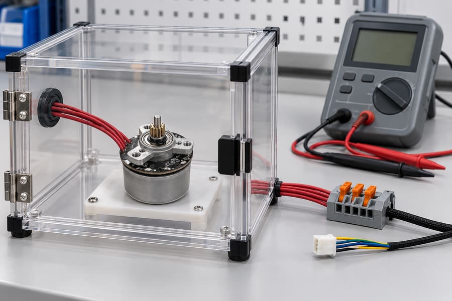
Illustrative test preparation keeps the motor and electronic interfaces clearly identified. The approved procedure must define circuit isolation, guarding and connections before any insulation test voltage is applied.
Before testing, obtain agreement on the AC or DC method, applied voltage, duration, connection arrangement, acceptance criteria, and treatment of abnormal results.
Voltage selection should follow the applicable engineering requirements and the approved insulation construction. Excessively severe testing can damage an otherwise usable winding.
Repeated dielectric withstand testing also requires consideration. The supplier-approved procedure should define whether repetition is permissible and under which conditions additional stress may be applied.
- Test boundary: Identify the winding circuits and conductive structures connected during the procedure.
- Electrical stress: Record the approved voltage, waveform type, application time, and permitted response.
- Equipment protection: Isolate Hall electronics, feedback devices, controllers, and other components unable to tolerate the applied stress.
- Operator protection: Require appropriate guarding, discharge procedures, controlled access, and verification that stored electrical energy has been removed.
- Result documentation: Record actual measurements or indications, failures, interruptions, and authorized deviations.
Connected electronics should never be assumed suitable for high-voltage winding tests. The complete test connection must be reviewed before applying voltage.
If a winding fails, avoid repeatedly increasing voltage or restarting the procedure without investigation. The failure should be evaluated against the approved disposition process.
Has Turn-to-Turn Insulation Integrity Been Verified with a Suitable Method?
Interturn insulation protects adjacent winding conductors from unintended electrical contact. Damage within this boundary can create localized electrical faults without involving grounded motor structures.
Because adjacent turns operate at different electrical potentials, their insulation must remain suitable for the voltage stress associated with the winding arrangement and drive conditions.
Why Can Interturn Insulation Defects Escape Other Electrical Tests?
Conductor coatings may become damaged during winding, insertion, forming, or handling. A defect between neighboring turns can remain electrically separate from the stator core.
In that situation, phase-to-ground insulation resistance may appear acceptable even though the winding contains a weakness between adjacent conductors.
Groundwall dielectric withstand tests face a similar limitation because their applied voltage does not necessarily produce the required stress across individual turn insulation.
An interturn short can change the effective winding characteristics and cause concentrated heating. Its effects depend on the number and position of affected turns.
Consequently, buyers should request a method specifically suited to detecting relevant interturn weaknesses rather than relying on unrelated electrical screening results.
Which Turn-Insulation Test Method Is Appropriate?
Surge comparison testing is one possible method, but its suitability depends on winding construction, electrical characteristics, applied stress, and the available measurement resolution.
Compact random-wound motors require particular care because procedures developed for larger winding systems may impose inappropriate stress or provide insufficient diagnostic sensitivity.
The supplier should approve the method after considering inductance, winding geometry, insulation construction, available terminal connections, and allowable test energy.
Acceptance criteria should address appropriate waveform characteristics, comparison conditions, and measurable abnormalities without assuming that every winding arrangement produces identical responses.
Connected sensors, controllers, and other sensitive electronic devices must be isolated where required. Applying a surge test through attached electronics can create damage unrelated to winding insulation quality.
When surge comparison is unsuitable, the engineering team should evaluate another appropriate verification method and document its limitations rather than forcing an unapproved test.
The following comparison identifies the distinct purposes of the three electrical insulation checks and the evidence needed to interpret their results.
| Test method | Insulation boundary | Primary purpose | Important limitation | Required evidence |
| Insulation resistance | Selected winding-to-ground or accessible circuit boundaries | Evaluate leakage resistance under defined conditions | Does not establish dielectric withstand or interturn strength | Measured resistance, voltage, duration, connections, and environmental conditions |
| Dielectric withstand | Specified groundwall or accessible phase-to-phase barriers | Verify withstand capability under an approved electrical stress | Does not independently verify insulation between neighboring turns | Applied voltage, duration, connections, acceptance criteria, and actual results |
| Turn-to-turn verification | Insulation between winding turns | Identify relevant interturn weaknesses using a suitable method | Detection capability depends on winding construction and test method | Approved procedure, applied stress, diagnostic records, and acceptance basis |
These methods should be selected as complementary checks. A satisfactory result from one does not remove the need to evaluate the other relevant insulation boundaries.
Is the Winding Insulation Compatible with Actual PWM Terminal Stress?
Insulation that passes production screening must also tolerate the electrical waveform applied during normal motor operation. PWM-driven applications require particular attention to repetitive voltage transitions.
The nominal DC bus voltage alone does not fully describe the voltage stresses experienced at motor terminals or within individual winding sections.
How Can PWM Operation Increase Winding Insulation Stress?
Rapid controller switching produces voltage transitions whose magnitude and rise time depend on the drive configuration, supply conditions, cable arrangement, and electrical characteristics.
In certain installations, cable impedance and reflected-wave effects can produce terminal voltage overshoot. The significance depends on cable length, switching speed, and system impedance.
Common-mode voltage can also stress insulation between energized winding circuits and grounded motor structures. Grounding and installation details influence the resulting electrical conditions.
Within the winding, the distribution of fast voltage transitions may differ from the distribution under steady or low-frequency conditions, affecting local interturn stress.
Repeated switching exposure should therefore be considered separately from conventional production dielectric withstand testing, which may use substantially different voltage characteristics.
Electrical stress and thermal stress should not be confused. PWM operation can contribute to losses and heating, but terminal overvoltage presents a separate insulation concern.
What Motor and Controller Information Should Be Reviewed Together?
The engineering review should identify the expected DC bus operating range, controller switching behavior, motor cable construction, cable length, grounding arrangement, and operating environment.
These inputs help determine whether the proposed winding insulation system is suitable or whether additional waveform measurements and verification are necessary.
Gian Transmission provides information about configurable BLDC motor drivers, but the suitability of any motor-controller combination must be established for the specific application.
- Supply conditions: Specify the anticipated DC bus voltage range, accounting for normal operation and relevant transient events.
- Switching behavior: Identify switching characteristics that influence terminal voltage rise time and repetitive electrical stress.
- Cable installation: Document relevant conductor arrangement, cable length, shielding, and grounding requirements.
- Measured waveform: Record terminal voltage behavior under representative conditions when application testing is required.
- Insulation review: Compare observed or appropriately calculated stress against approved winding insulation requirements.
Where testing is necessary, use suitable high-bandwidth measurement equipment and properly rated connections. The measurement arrangement should avoid introducing unacceptable electrical or personnel hazards.
If application stress exceeds the approved insulation envelope, possible changes include controller settings, cable configuration, filtering, or a revised motor insulation design.
Before granting final approval, evaluate how each proposed modification could influence motor performance, thermal characteristics, electrical compatibility, and installation requirements.
Documenting the actual drive conditions is more useful than assuming that identical nominal motor voltages guarantee equivalent insulation stress across different installations.
Is Conditioned or Endurance Test Evidence Traceable to the Proposed Winding Design?
Initial inspection and electrical testing describe insulation condition at particular points in manufacturing. They do not independently establish performance after environmental exposure or repeated operation.
Qualification evidence should therefore reflect the thermal, mechanical, and electrical stresses relevant to the intended application, using procedures agreed upon before testing.
Which Conditioning and Endurance Tests Are Relevant?
Thermal cycling can expose weaknesses associated with differential material expansion, winding restraint, and repeated temperature changes. Select test conditions that represent the environmental stresses the motor is expected to encounter during operation.
Humidity conditioning may be relevant when moisture exposure could influence leakage behavior or material performance. The procedure should specify exposure conditions and measurement timing.
Mechanical vibration can challenge conductor restraint, lead protection, and physical insulation barriers. Its relevance depends on the motor installation and expected vibration environment.
Operational endurance testing can combine electrical loading, winding heating, and mechanical effects under representative duty conditions, although it cannot automatically cover every possible field environment.
Accelerated testing requires particular care. Increasing stress may change failure mechanisms, so accelerated results should not be converted into service-life claims without a justified relationship.
Define exposure severity, duration, sequence, sample quantity, and operating state. This allows the resulting evidence to be interpreted against an established engineering objective.
How Should Insulation Performance Be Evaluated Before and After Conditioning?
Baseline measurements should be collected before exposure using the approved methods. These establish reference values for later comparison and help distinguish existing defects from conditioning-related changes.
After conditioning, repeat suitable electrical checks and physical inspections under defined conditions. Compare changes rather than relying only on isolated pass-or-fail statements.
Possible findings include insulation cracking, displaced barriers, conductor abrasion, increased leakage, or other electrical abnormalities. Evaluate the significance of each observed condition against the established and approved acceptance criteria.
Tests involving elevated electrical stress should remain within supplier-approved procedures. Conditioning does not justify applying arbitrary withstand or surge voltages to an assembled winding.
Where samples fail, record the failure stage, observed characteristics, test conditions, and investigation findings. Unexplained failures should not be hidden within averaged results.
Sample quantity also affects interpretation. Passing a limited number of specimens provides evidence for those tested conditions, not a guarantee of population-wide reliability.
What Traceability Is Needed Before Production Approval?
Qualification results should identify the winding construction actually tested, including drawing revision, insulation material specifications, processing requirements, and individual specimen identification.
Routine production checks and design qualification serve different purposes. A production insulation resistance test should not be represented as equivalent to completed environmental endurance qualification.
Material substitutions, conductor changes, revised winding patterns, or altered impregnation procedures may affect insulation performance and should trigger a documented engineering impact assessment.
The following table organizes the conditioned verification evidence needed to support a traceable approval decision without imposing universal electrical or endurance limits.
| Verification stage | Evidence required | Recorded conditions | Acceptance basis |
| Baseline inspection | Winding photographs or inspection records and initial electrical measurements | Sample identity, instrument, temperature, test connections, and procedure revision | Approved initial workmanship and electrical requirements |
| Environmental conditioning | Exposure records and observations during conditioning | Temperature, humidity, vibration, duration, or other specified stresses | Application-defined conditioning procedure |
| Post-conditioning verification | Electrical results compared with baseline measurements | Measurement conditions, timing, and instrument information | Approved post-conditioning limits and permitted changes |
| Physical condition review | Inspection findings, damage records, and failure investigation | Inspection locations and observed abnormalities | Defined physical acceptance and defect disposition criteria |
| Design traceability | Material records, winding drawings, sample identification, and revision history | Manufacturing configuration and changes affecting tested specimens | Approved design configuration and engineering change requirements |
Before release, the supplier and buyer should agree on which qualification evidence applies to the approved winding revision and which production checks will remain mandatory.
The final engineering file should contain the approved winding and insulation drawings, material specifications, thermal assessment, workmanship criteria, and relevant inspection records.
It should also contain supplier-approved electrical test procedures, measured insulation resistance and withstand results, appropriate interturn verification records, and documented isolation requirements for sensitive electronics.
Complete the record with application PWM stress information, conditioned-test results, specimen and production traceability, approved deviations, and the responsible engineering approvals tied to the final motor configuration.