
Microstepping sets the spacing of commanded electrical positions; it does not by itself establish the accuracy of a loaded mechanism. To evaluate positioning performance, measure where the output actually settles across the working travel, in both directions, at the intended current and load. The useful result is an error map with repeatability and test conditions, rather than a calculation based only on pulses per revolution.
What Does the Microstep Calculation Really Describe?
For a motor with 200 full steps per revolution, a setting of 16 microsteps per full step creates 3,200 command increments per revolution. If an ideal screw advances 4 millimeters per revolution, the nominal command increment is 0.00125 millimeter. This illustrative arithmetic describes the command grid, not a verified 1.25-micrometer positioning capability.
The physical output also depends on magnetic behavior, phase-current regulation, friction, transmission error, and elastic movement under load. Some of those effects are larger than one command increment. A controller can therefore accept finer coordinates without the mechanism producing equally fine, independently distinguishable movements.
Use the Gian hybrid stepper motor range as the starting point for a motor inquiry, then request performance evidence for the proposed drive and transmission. A frame size or subdivision setting alone is not sufficient to approve the final axis. The motor, electronics, mechanism, and measurement setup form the system being evaluated.
Which Performance Terms Should the Specification Separate?
Separate command resolution, measured position error, repeatability, and reversal behavior. Position error compares a measured location with its intended reference. Repeatability describes the spread obtained when returning to a location under specified conditions; a repeatable location can still be consistently displaced from the target.
A reversal test adds another question: does the same command produce a different result depending on the direction of approach? Mechanical play, friction, and load-dependent deflection can all contribute. Increasing the number of microsteps does not automatically remove those effects.
NIST’s terminology for accuracy and repeatability is useful when naming the reported quantities. Define the numerical error and spread explicitly instead of using precision as a catch-all label. This makes supplier data easier to compare with the machine requirement.
| Quantity | What the Test Establishes |
| Command increment | Smallest coordinate change requested by the controller |
| Position error | Difference between measured and intended location |
| Repeatability | Spread of repeated arrivals under stated conditions |
| Reversal difference | Change associated with approaching from opposite directions |
| Settling time | Time required to remain within the agreed position band |
Why Can Small Commands Produce Uneven Movement?
The rotor settles where electromagnetic torque balances the applied disturbance. A small change in commanded current distribution may not immediately overcome friction or an external load. Several small commands can sometimes be followed by a larger observed movement, particularly in a mechanism with substantial friction.
Microstepping still offers a practical benefit when smoother excitation improves the axis’s motion. Its finer command grid is valuable only to the extent that the assembled mechanism can use it. Compare candidate settings against the application’s measured output requirements before selecting a subdivision.
For background on excitation patterns, see the existing stepper motor control guide. Keep that basic explanation separate from the acceptance claim. A description of how a driver generates intermediate electrical positions is not a substitute for measuring loaded output motion.
How Should a Small-Move Test Be Organized?
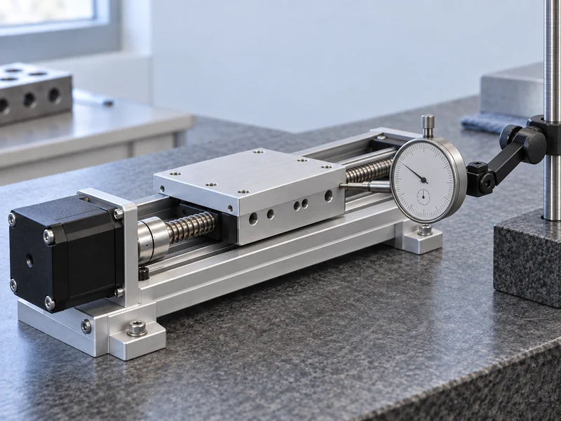
Start with a stable, independent position reference at the actual output. Select an instrument with sufficient resolution, suitable contact force where relevant, and a mounting arrangement that will not follow the motor’s movement. Record the instrument identity and the uncertainty considerations that matter at the proposed tolerance.
Choose a short travel region and command a sequence of equal increments without reversing direction. Record the settled position after each command, then repeat the sequence at other regions of the travel. Differences between regions can reveal that a successful demonstration at one location does not represent the entire mechanism.
Repeat the experiment with a practical set of subdivision settings. Hold the relevant current definition, load, acceleration, and settling criterion constant, while documenting any driver behavior that changes with the mode. Otherwise, a result attributed to microstepping may actually come from a change in current or timing.
Do not average away the small-move behavior before inspecting it. A smooth best-fit line across a long distance can conceal irregular individual increments. For an application that meters tiny movements, the largest local deviation may matter more than the average slope.
How Should Full-Travel and Reversal Tests Differ?
A full-travel test checks whether positioning remains acceptable at multiple working coordinates. Move to each coordinate from one direction, record the result, and then repeat using the opposite approach. Keep the reference procedure consistent so that a changing origin does not contaminate the comparison.
The output should be measured where the process acts. An encoder on the motor shaft can provide useful information, but it does not directly observe every downstream error in a screw, belt, coupling, or gearbox. A motor-side reading and a load-side reading answer different questions and should be identified accordingly.
For each coordinate, report the signed error and the spread of repeated arrivals. A single absolute maximum can serve as a release criterion, but the underlying map is more useful for engineering. It shows whether the problem is concentrated near one end, follows a periodic pattern, or changes primarily with direction.
If the required error band cannot be maintained with the selected arrangement, consider mechanical improvements, feedback, or a different motion architecture. The existing servo versus stepper comparison provides a broader starting point. A change in architecture should still be justified by the measured requirement rather than a general technology preference.
Which Loads and Temperatures Belong in the Test?
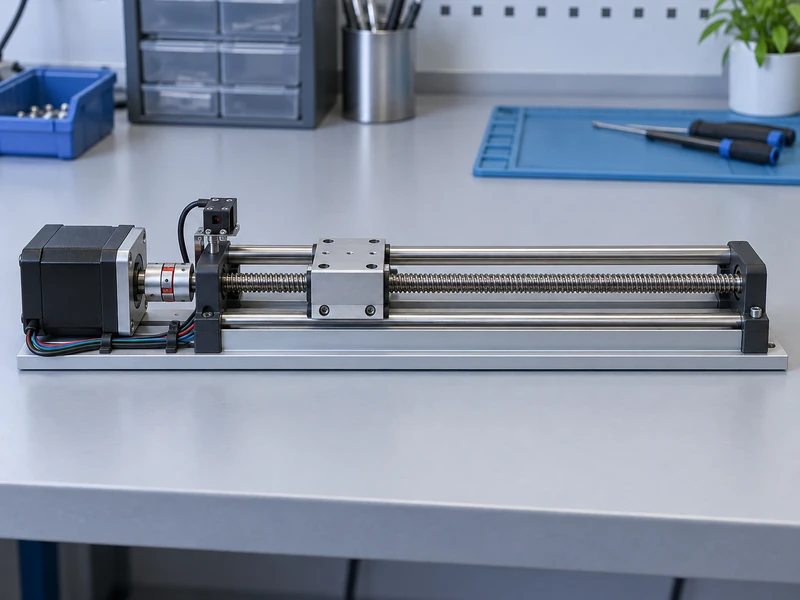
Test the loads that can materially change friction, deflection, or rotor equilibrium. A carriage carrying its nominal payload is not necessarily the worst case if cable routing, seal drag, or process contact varies across the cycle. Include those disturbances in the test description so the next engineer can reproduce them.
Compare cold-start behavior with operation after a representative warm-up. Use a stated settling time and temperature observation rather than assuming that a fixed number of minutes produces the same condition on every bench. Record whether the motor remains energized during pauses.
The stepper motor driver must maintain the intended current regulation under those conditions. Confirm whether its current setting is stated as peak or RMS and whether automatic idle reduction is active. An unnoticed current change can alter the result while leaving the command resolution unchanged.
For a moving application, add the relevant speed and acceleration to the test plan. A stationary small-move demonstration does not establish dynamic tracking performance. The article on stepper inertia selection explains why the load’s dynamic demand also needs consideration.
How Should Results Guide the Final Microstep Setting?
Choose the lowest subdivision setting that meets the measured motion and smoothness requirements with adequate command-rate capability. Higher settings may be appropriate, but they should earn their place through observed benefit. Excess command rate can burden the controller without correcting a mechanical error.
For example, a project might find that moving from full steps to moderate microstepping improves settling while a further increase does not reduce the output error. That is a hypothetical decision pattern, not a prediction for a particular Gian motor. The correct choice remains the one supported by the actual combination and its operating conditions.
Issue the final report with the motor and driver revisions, current settings, transmission details, coordinate map, load conditions, and measurement method. State both the accepted operating range and any conditions that were not tested. This turns a resolution claim into evidence that the machine can position its load where the process needs it.