
Two-plane balancing controls both resultant force and couple unbalance, but a long inrunner rotor is not automatically flexible. Its dynamic behavior must be assessed across the intended speed range and support conditions.
A useful procurement specification identifies the tested assembly, correction geometry, residual limits, test conditions, measurement evidence, and controls for reassembly, maintenance, and design changes.
Why Does a Long Inrunner BLDC Motor Need Two-Plane Balancing?
For motor configuration context, review Gian Transmission’s custom inrunner BLDC motor configurations and its brushless DC motor information. These pages provide context for motor and shaft interfaces, not a universal balancing grade or an automatically included balancing report.
Understand Static Unbalance and Couple Unbalance
Static unbalance exists when the rotor’s mass center does not lie on its rotational axis. During rotation, this eccentricity produces a centrifugal force whose magnitude increases with speed.
Couple unbalance is different: unbalanced mass distributions at separated axial positions create a rotating moment. Their forces can cancel as a resultant while still producing a significant couple.
An actual rotor may contain both components. A single correction plane can reduce a resultant force, but it cannot generally remove an independent couple generated by axially separated mass errors.
Two-plane balancing uses correction actions at two axial locations to control the force and couple components of a rigid rotor. The correction amounts and angular positions must be considered together.
Why Static Balancing Alone May Be Insufficient
A rotor that rests without a preferred heavy position has not necessarily passed a dynamic balance requirement. Static assessment does not fully reveal how mass errors separated along the rotor length behave during rotation.
This distinction matters for long inrunner assemblies because magnets, sleeves, spacers, and other rotating features may distribute mass along an extended axial span. Their combined effect cannot be judged from rotor length alone.
The specification should therefore state whether the required result is static balance, single-plane dynamic balance, or two-plane dynamic balance. For a rotor requiring control of both force and couple, define two-plane acceptance explicitly.
Determine Whether the Rotor Is Rigid or Flexible
Evaluate Rotor Geometry and Dynamic Behavior
Rotor length is one input, not a classification rule. Diameter, shaft stiffness, material, mass distribution, bearing span, support stiffness, and operating speed all influence the rotor’s dynamic response.
The relevant question is whether the rotor behaves approximately as a rigid body throughout the specified balancing and operating range. A rigid-rotor model assumes deformation does not materially change the unbalance response being corrected.
Review intended speeds against relevant bending critical speeds, accounting for bearing and housing compliance in the assembled support system.
Distinguish Rigid-Rotor and Flexible-Rotor Balancing
For a rigid rotor, two-plane balancing can normally represent the principal force and couple unbalance with two correction planes. The selected procedure still needs to match the rotor geometry and fixture arrangement.
A flexible rotor can bend appreciably as speed changes. Its vibration response may vary with speed and mode shape, so correction at two planes under a rigid-rotor assumption may not control every operating condition.
Where flexible behavior is credible, the supplier and buyer should agree whether modal analysis, additional correction planes, or another engineered method is required. The purchase specification should record the basis for that decision.
Separate Unbalance from Other Mechanical Problems
Balancing addresses mass distribution around a rotational axis. It does not straighten a bent shaft, correct mounting misalignment, repair a damaged bearing seat, or move an unsuitable critical speed.
These conditions can produce similar vibration symptoms, so acceptance should not rely on vibration reduction alone. Shaft geometry, bearing interfaces, assembly alignment, and rotor integrity need their own inspection criteria.
Define the Rotor Assembly, Mass, and Operating Conditions
Specify the Complete Balancing Configuration
Identify exactly what the supplier must balance. The scope may be a bare rotor, a rotor core with magnets, or a complete assembly containing sleeves, spacers, fans, encoder targets, and other rotating hardware.
List included and excluded components. If a component is installed after balancing, assess whether its mass and position can change the accepted result.
Document any difference between the test configuration and the intended service assembly, then define how its effect will be evaluated.
Provide Rotor Mass and Operating Information
Provide the actual or controlled nominal mass of the assembly being balanced, together with the drawing revision that defines its geometry. If mass changes between revisions, require the balancing limit to be reviewed.
State rated speed, maximum intended continuous speed, and relevant transient or intermittent speeds. Describe duty cycle, acceleration, temperature, and mechanical loading where they affect the balancing decision.
Identify the service bearing support and installation arrangement. The supplier can use this information to determine whether the selected balancing approach and test setup are appropriate for the intended application.
Establish Key and Coupling Conventions
State whether the rotor is balanced with a key, without a key, or with another defined coupling arrangement. Where a key convention is needed, specify the agreed full-key, half-key, or no-key condition.
A default shop convention may not match the final assembly. Keys, couplings, fans, and other attachments can change mass distribution and angular reference.
Identify components added during integration so the acceptance record describes the tested configuration, not merely the motor model.
Specify Correction Planes, Shaft Datums, and Correction Methods
Define the Axial Locations of Both Correction Planes
Name the planes A and B and define their axial locations from a drawing datum. State the distance between the planes and identify the physical features that locate each correction region.
“Front” and “rear” are ambiguous when drawings or viewing directions change. Use dimensioned references and confirm both correction regions remain accessible after assembly.
Specify Correction Radii and Permitted Correction Areas
Identify the effective correction radius or permitted radial range for each plane. Because residual unbalance is a mass-radius quantity, the available radius affects the correction mass required.
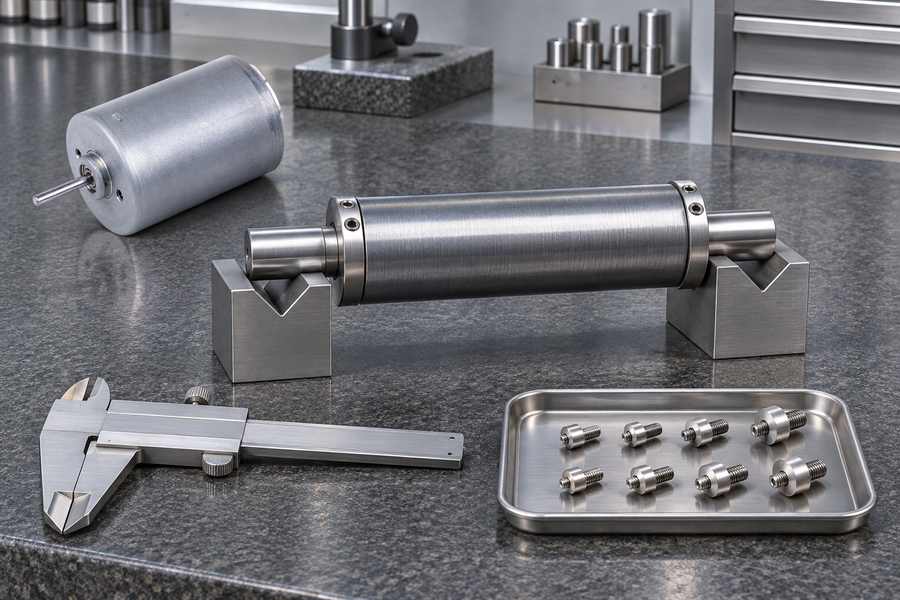
Mark approved pockets or surfaces and consider clearances to magnets, sleeves, bearings, windings, housings, and nearby rotating parts. Define restricted areas where removal could weaken a feature.
Define Permitted Material Addition and Removal
For removal, identify permitted drilling or machining areas and any deburring or surface-protection requirements. For addition, state whether approved weights or another engineered retention method are allowed.
Corrections must preserve shaft strength, magnet retention, rotor integrity, electrical clearances, and mechanical containment. Obtain engineering approval before altering a structural feature.
Establish Shaft Datums, Journals, and Balancing Tooling
Identify the shaft centerline, bearing journals, mounting surfaces, and datum relationships that establish the rotational reference.
Specify the arbor, fixture, or support arrangement. It should locate the rotor repeatably without avoidable eccentricity, distortion, or inconsistent clamping. Document any difference from service support conditions.
Specify Shaft Runout Separately from Residual Unbalance
Define journal runout and shaft straightness requirements separately, including measurement locations, datum references, and applicable drawing criteria.
Runout is geometric variation at a measured surface; residual unbalance is a mass-distribution error. A balancing report does not prove shaft straightness or journal conformity, so retain separate inspection results.
Establish Permissible Residual Unbalance for Both Planes
Define the Acceptance Limit for Each Correction Plane
State the maximum permissible residual unbalance for plane A and plane B separately. Include the unit, angular reference, applicable rotor configuration, and whether the stated value is a maximum magnitude.
A statement such as “dynamically balanced” is insufficient because it defines neither the measured quantities nor acceptance.
Set limits from rotor mass, speed, support conditions, vibration sensitivity, and application risk; do not copy one generic grade into every specification.
Understand the Permissible Residual Unbalance Calculation
For a rigid-rotor calculation, use G in mm/s, rotor mass in kg, speed in rpm, and permissible residual unbalance in g·mm:
Uper = 9549 G m / n
Here, Uper is permissible residual unbalance in g·mm, G is the selected balance quality grade in mm/s, m is rotor mass in kg, and n represents the rotational speed expressed in revolutions per minute (rpm).
The relationship applies to rigid-rotor calculations using the specified measurement units. G must be selected for the application; the formula does not establish a universal grade or acceptance limit.
The calculated value applies to the rotor as a whole under the stated model, not automatically to each plane.
Allocate the allowance using rotor geometry, plane separation, correction radii, and the agreed method; do not assume an equal split.
For a flexible rotor, this rigid-rotor relationship may not define acceptance adequately. Modal response and speed-dependent behavior need an appropriate evaluation.
Account for Measurement Uncertainty and Repeatability
Specify measurement resolution and uncertainty relevant to acceptance. The system must distinguish a passing result from the stated limit with adequate confidence.
Define repeatability under the same configuration and setup. Agree how borderline results are assessed, whether uncertainty is reported separately, and who approves deviations.
Specify Balancing Test Speed and Measurement Conditions
Distinguish Test Speed from Operating Speed
State the balancing test speed required by the approved procedure and distinguish it from rated speed and maximum operating speed. These values serve different purposes and should not be used interchangeably.
A rigid rotor may be balanced at a suitable lower test speed when the chosen method and equipment support the specified result. Low-speed balancing does not, by itself, prove that every operating-speed vibration issue has been resolved.
For a flexible rotor, speed-dependent deformation may change the response. The supplier and buyer should define whether additional modal or operating-speed evaluation is needed rather than assuming a two-plane low-speed result is sufficient.
Define Additional Requirements for Flexible-Rotor Evaluation
Where flexible behavior is established, identify the modes and speed range relevant to the required evaluation. Agree the correction approach and measurement evidence before testing begins.
High-speed evaluation requires an engineered arrangement, suitable containment, instrumentation, and approved procedures. Do not use improvised spin tests or unapproved overspeed trials.
Record the Actual Balancing Conditions
Record actual test speed, rotor configuration, support arrangement, tooling, and measurement setup. Identify the equipment used and the reference direction for angular readings.
Document deviations from the approved procedure and assess whether they affect comparability or acceptance. A report should describe what was actually tested, not simply repeat the intended test conditions.
Require Traceable Before-and-After Balancing Reports
Record Initial Unbalance Measurements
Require initial unbalance magnitude and angular position for both correction planes before correction. The report should identify the reference mark, viewing direction, rotation convention, and units used for phase readings.
Preserving initial vectors makes the correction process traceable. It also allows a reviewer to distinguish the original condition from the final residual result rather than receiving only a pass statement.
Document Correction Actions and Final Results
Record each correction location, radius, method, and amount of material added or removed. If multiple correction operations occur, preserve enough detail to reconstruct the sequence and final configuration.
Report final residual-unbalance magnitude and angular position separately for planes A and B. Compare each value with its own specified limit and identify the acceptance result for each plane.
Include shaft runout and dimensional inspection results as separate records where required. Do not combine geometric inspection values with residual-unbalance readings or imply that one proves the other.
Define Required Report Information
Link the report to a unique rotor identity, drawing revision, tested configuration, and key or coupling convention. Retain the datum, fixture, support arrangement, initial and final vectors, correction details, test speed, equipment identification, uncertainty, repeatability, and disposition.
| Report item | Information to retain |
| Rotor identity | Part number, serial number, and drawing revision |
| Test configuration | Included components, key convention, fixture, and support arrangement |
| Initial condition | Magnitude and angular position for both correction planes |
| Correction record | Plane, radius, location, method, and correction amount |
| Final condition | Residual magnitude and angular position for each plane |
| Measurement evidence | Test speed, equipment identification, uncertainty, and repeatability |
| Disposition | Acceptance against individual limits and approved deviations |
Control Reassembly, Maintenance, and Design Changes
Preserve the Approved Balanced Configuration
Preserve correction marks and control rotor orientation, component indexing, retaining hardware, and the specified key or coupling arrangement during reassembly.
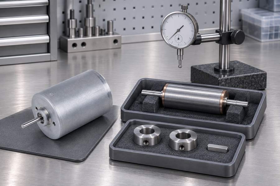
Inspect for damage, contamination, or displaced components. If the service assembly differs from the tested configuration, document the difference and define verification before release.
Identify Changes That May Require Rebalancing
Review shaft replacement or repair, machining, magnet or sleeve changes, and modifications to keys, couplings, fans, or other included rotating hardware. These changes may alter mass distribution or datum relationships.
Establish Reinspection and Change-Control Requirements
Define which changes require complete rebalancing, dimensional verification, or documented engineering review. Link new records to the original rotor identity and reassess the method and limits when mass, geometry, support, or speed changes.
Prepare a Practical Two-Plane Balancing Specification for Procurement
Information Buyers Should Include in an RFQ
A useful request for quotation defines the required result and gives the supplier enough information to propose a method and identify unresolved engineering inputs.
- Rotor identification: Part number, serial number where available, drawing revision, and assembly definition.
- Rotor behavior: Rigid-rotor or flexible-rotor determination, including the engineering basis or an agreed responsibility for assessment.
- Operating conditions: Rotor mass, rated and maximum intended continuous speeds, duty cycle, and relevant service conditions.
- Correction geometry: Plane A and B axial locations, correction radii, permitted areas, and restricted features.
- Shaft interfaces: Datum definition, journal dimensions, runout requirements, and required tooling or support references.
- Assembly convention: Included components, key condition, coupling arrangement, and any components installed after balancing.
- Acceptance criteria: Separate permissible residual-unbalance limits and units for both correction planes.
- Test conditions: Balancing method, actual test speed, fixture arrangement, and measurement requirements.
- Reporting: Initial and final vectors, correction records, equipment identification, uncertainty, and repeatability evidence.
- Change control: Rebalancing and verification requirements after repairs, reassembly changes, or design revisions.
Verify the Supplier’s Proposal Before Approval
Confirm that the fixture uses the specified shaft datums and both correction regions are accessible. Check that correction methods protect structural and magnetic-retention features.
Verify separate residual limits, allocation, measurement capability, uncertainty, and repeatability. Confirm the assembly, key convention, test speed, reporting scope, and responsibility for any flexible-rotor assessment.
List exclusions explicitly so unprovided tests or deliverables are not mistaken for included work.
Gian Transmission’s custom inrunner dimensions and shaft-interface capabilities can be considered when defining the motor geometry and mounting references. Balancing procedures, acceptance limits, and report deliverables should remain separately specified and agreed.
Set Delivery Acceptance Around Records, Not a Generic Pass Statement
Before release, match the delivered rotor to its drawing revision and tested configuration. Verify initial and final vectors for both planes and compare each residual value with its own limit.
Review correction records, uncertainty, repeatability, and approved deviations. Resolve missing evidence before acceptance, then retain the specification, drawing, balance report, runout inspection, and change history under one rotor identity.