
Dual encoders can help a controller detect and correct some position error across a gearbox, but they do not remove the mechanical clearance. The motor encoder measures motion before the reducer, while the output encoder measures motion after it. Whether that extra information improves the robot depends on the transmission, sensor mounting, control architecture, tuning, and required response time.
The useful question is therefore which error the second encoder will observe and how the controller will respond to it. A second sensor is valuable when it closes a specific measurement gap. It is less useful when the dominant error occurs elsewhere in the mechanism or the drive cannot use its signal properly.
What Can a Motor Encoder Actually See?
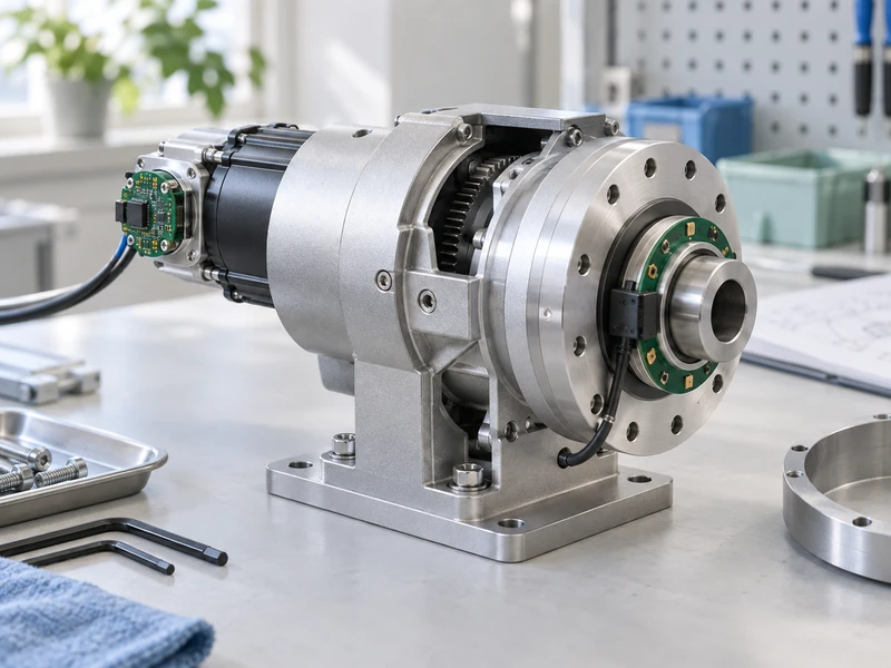
A motor encoder observes the motor shaft or rotor position at its mounting location. Dividing that angle by the reduction ratio produces an idealized estimate of output angle. That estimate assumes the transmission transfers motion exactly as modeled.
Real transmissions introduce departures from that ideal relationship. Clearance, elastic deformation, friction, mounting movement, and transmission error can create a difference between the calculated output angle and the actual output position. A motor encoder alone cannot directly measure that difference.
For example, the motor may move while the gear teeth cross a reversal clearance, with little immediate movement at the output. Conversely, an external load may displace the output within available play while the motor angle changes very little. These are mechanical states that more motor-side encoder counts cannot resolve by themselves.
GIAN’s explanation of planetary gearbox backlash provides background on the physical sources. Start there when deciding whether the primary problem is measurement, mechanics, or both.
What Does an Output Encoder Add?
It directly measures the output relative to its own stationary reference. The controller can compare that measurement with the target and with the motor-side estimate. This makes some transmission behavior observable that was previously hidden behind the gear ratio calculation.
The mounting reference is critical. If the encoder stator moves with a flexible bracket, its reading includes that bracket’s behavior. If the tool bends downstream of the measured flange, the encoder does not directly observe the tool-tip deflection.
Draw both sides of the encoder interface so its angular reference is unambiguous. Identify the rotating element, stationary reference, coupling, and any flexible structure between the sensor and the actual task point. This prevents a load encoder from being credited with measuring the entire robot when it measures only one joint interface.
The AGMA robotics backlash white paper describes dual feedback as one approach to transmission-related position errors and notes the added control complexity. The extra sensor provides information; the control system still needs to use it effectively.
Why Is Dual-Loop Tuning More Demanding?
The controller is acting through a mechanical connection that may be compliant and nonlinear. When torque reverses across clearance, the relationship between motor motion and load motion changes. Increasing position gain can therefore produce oscillation or harsh contact instead of better accuracy.
A common architecture uses motor-side feedback for an inner motion loop and output feedback for an outer position loop. The specific implementation and bandwidths must follow the drive’s supported design. Do not assume that connecting a second encoder automatically enables an appropriate dual-loop mode.
A Galil motion-control manual hosted by the University of Hawaii distinguishes continuous dual-loop compensation from endpoint correction and discusses their different limitations. Its configuration instructions are specific to that controller; the broader lesson is to match the feedback method to the motion requirement.
When evaluating a BLDC motor driver, ask explicitly about dual-feedback support, accepted sensor interfaces, synchronization, diagnostics, and commissioning. A general statement that a drive accepts an encoder does not answer those questions.
Is Endpoint Correction Enough?
It may be enough for a task that only requires accurate settled positions, but it is not equivalent to accurate motion throughout the path. A system can arrive, measure the remaining error, and make a correction after the main move. That strategy can add settling time and may not suit continuous inspection or contact tasks.
Define when the error matters. A pick-and-place operation may tolerate a brief correction before gripping, while a tracing task may require bounded error continuously. A reducer that meets the gripping cycle may miss the tracing requirement because error is assessed at different moments.
| Task Requirement | Potential Benefit of Output Feedback | Remaining Limitation |
| Accurate final position | Correct measured endpoint error | Correction takes time |
| Smooth reversal | Observe delayed output response | Clearance and contact transitions remain |
| External disturbance rejection | Detect output displacement | Response is limited by mechanics and control |
| Accurate tool-tip location | Improve measured joint angle | Link and tool deformation may be unmeasured |
Write separate limits for moving error, final error, and settling time. Reporting only the best stationary position can hide a system that vibrates or overshoots during the rest of its cycle.
Why Can More Encoder Counts Still Leave Position Error?
A finer count spacing does not establish a smaller angular measurement error. Mounting eccentricity, alignment, sensor nonlinearity, interpolation, signal quality, and calibration can all affect the latter.
Consider the complete sensor chain. A high-resolution encoder attached through a flexible coupling may provide many counts while still reporting a distorted relationship to the load. A robust lower-resolution arrangement may be more useful if it meets the required measurement uncertainty and repeatability.
Also examine timing. The motor and output measurements need to represent comparable moments when used together during motion. A delay mismatch can look like transmission error even when the mechanism is following the intended path.
GIAN’s guide to robotics gear motor selection places feedback within the wider mechanism decision. The sensor specification should follow the tool-error budget rather than an isolated desire for the largest bit count.
What Should Be Tested Before Adding the Second Loop?
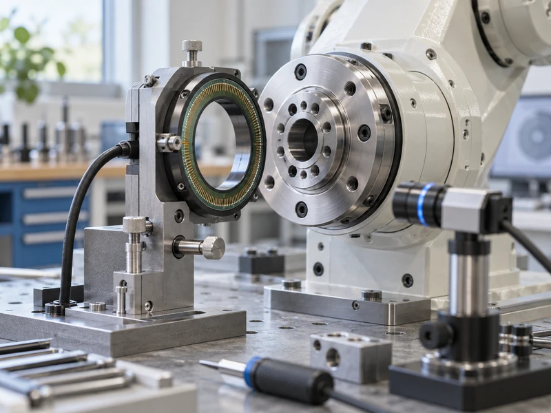
Characterize the mechanical assembly first. Measure reversal behavior, loaded deflection, friction, and repeatability with clearly defined conditions. This provides a baseline and identifies faults that feedback should not be asked to conceal.
Commission the motor-side system within conservative limits, verify both sensor directions and scales, and check their relationship through the travel range. Then follow the drive manufacturer’s procedure for enabling and tuning the additional feedback. Do not copy gains from another joint merely because its motor is the same size.
Use a test sequence that exposes the application demands:
- Approach identical targets from both directions.
- Repeat the moves under representative external load.
- Compare cold and warmed operation.
- Introduce permitted changes in tool mass and configuration.
- Check sensor fault responses and recovery behavior.
Keep the raw position and command records where practical. They reveal whether a lower final error was purchased with longer settling, larger oscillation, or higher current. Those tradeoffs can matter more than the single best position result.
What Can the Difference Between the Two Encoders Reveal?
After accounting for ratio, direction, and offsets, the difference between the signals can help characterize the transmission. Plot that difference against applied load, motion direction, output position, and temperature. Patterns may help distinguish repeatable geometric effects from load-dependent deformation or intermittent measurement faults.
The difference is not automatically a direct backlash measurement. Sensor error, timing mismatch, coupling movement, and elastic deformation can all contribute. Use controlled tests to isolate these effects before reporting a mechanical clearance value.
Tracking Changes in the Motor-to-Output Relationship?
They can provide a useful baseline for the particular assembly. Repeating the same diagnostic movement over time may reveal a change in the relationship between motor and output motion. Investigate that change alongside temperature, current, noise, and physical inspection.
Avoid assigning a universal wear threshold without validation. A different tool, new cable routing, altered controller settings, or a sensor recalibration can also change the recorded pattern. Preserve the configuration and test conditions with every comparison.
For a production system, define what happens when a diagnostic limit is exceeded. The response might be a maintenance inspection or a controlled stop, depending on the machine requirements. The extra encoder is most useful when its data supports a documented decision rather than simply adding another number to a dashboard.
When Should the Gearbox Be Improved Instead?
Improve the mechanism when clearance, flexibility, or wear prevents the required dynamic behavior despite appropriate sensing and control. Feedback cannot eliminate the time needed to traverse a mechanical gap or repair a moving bearing seat. A better transmission may reduce both tuning effort and residual error.
Compare the cost of a mechanically improved servo motor assembly with the full cost of extra sensing and integration. GIAN’s discussion of backdrivable actuator gearing is also relevant if changing reduction would affect interaction behavior.
The strongest design combines adequate mechanics with feedback that measures the errors relevant to the task. Treat dual encoders as a deliberate control architecture. Their value comes from better information and a validated response, not from making gearbox backlash physically disappear.