
BLDC regenerative braking can raise the DC bus voltage when a moving load returns energy through the motor controller faster than the system can absorb it. Preventing overvoltage requires a verified destination for that energy: a suitable battery, a regenerative power supply, available bus capacitance, another consuming axis, or a controlled braking resistor. Motor wattage and the power supply’s output-current rating alone do not establish braking compatibility.
Why Does a BLDC Drive Trip During Deceleration?
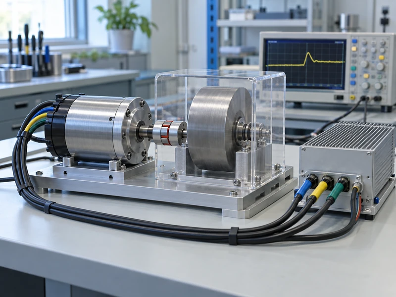
During a controlled stop, the load can drive the motor while the controller commands torque against its rotation. Depending on the control strategy, electrical energy then reaches the DC link, charging its capacitors and increasing the voltage. A source-only supply may deliver acceleration current successfully yet be unable to accept this returning power.
Typical clues include a fault that appears only during rapid stops, a supply that resets during downward travel, or a machine that works on a battery but trips on a bench supply. These observations justify checking regeneration, but they are not a diagnosis by themselves. Wiring inductance, switching transients, and unstable control can also produce voltage disturbances.
Start the investigation at the drive’s DC input terminals and correlate voltage with speed, current, and fault timestamps. A display on the power supply may miss a short event or show a different voltage because of the connecting cable.
Is Every Electronic Brake Regenerative?
No: a stop command does not identify where the energy goes. Different controllers may coast, dissipate energy through motor winding losses, return it to the DC bus, or combine these behaviors across the speed range.
| Stopping Method | Energy Destination | What to Verify |
| Coasting | Mechanical and electrical losses during run-down | Whether the resulting stopping distance is acceptable |
| Motor short-circuit braking | Primarily motor and switching-device losses | Permitted current, temperature, and speed-dependent braking torque |
| Regeneration to the DC bus | Battery, supply, capacitor, or another load | Available absorption capacity throughout the operating cycle |
| Bus chopper with resistor | Heat in a controlled resistor circuit | Switch ratings, resistor pulse capacity, and cooling |
When comparing BLDC motor drivers, request the braking-mode description and fault response for the specific model and firmware. A product category description cannot confirm four-quadrant operation or compatibility with an external chopper.
Mechanical backdrivability is a separate requirement: it describes how the output can drive the transmission. GIAN’s guide to gear ratios for backdrivable BLDC actuators provides useful context before evaluating the electrical return path.
How Much Braking Energy Must the System Handle?
Estimate the energy released by the actual motion, then assess how quickly it arrives and how often the event repeats. Include rotating components, translating loads, and changes in gravitational potential energy where applicable.
- Rotating load: energy released is ½ × J × (initial angular speed² − final angular speed²).
- Translating load: energy released is ½ × m × (initial linear speed² − final linear speed²).
- Descending load: potential energy released is m × g × vertical drop.
Use consistent SI units and avoid counting the same load twice through both its physical motion and an equivalent reflected inertia. Losses reduce the energy reaching the bus, but assuming an unverified recovery efficiency can understate the required capacity. For initial screening, evaluate a conservative energy case and refine it with measurements.
What Does a Simple Example Reveal?
Consider an illustrative rotary mechanism with an equivalent inertia of 0.002 kg·m², referred to the shaft rotating at 3,000 rpm. Stopping that shaft releases approximately 98.7 J of kinetic energy. These are assumed design values, not GIAN product specifications or test results.
A 0.5-second stop gives an average mechanical braking power of about 197 W over the stopping interval. If the mechanism starts one such stop every five seconds, the corresponding cycle-average energy rate is about 19.7 W. The instantaneous electrical peak and the energy actually absorbed by a resistor still depend on the motion profile and losses.
This difference explains why a low average heat load can coexist with a demanding braking pulse. Review the motor’s thermal duty as well, using the distinction between peak torque and continuous torque when interpreting repeated deceleration current.
Can Extra DC Bus Capacitance Solve the Problem?
Extra capacitance can buffer a limited energy pulse if sufficient voltage headroom exists. Its useful capacity is the energy difference between the starting voltage and the chosen upper operating limit, not its total stored energy at that limit.
The University of Texas explanation of capacitor energy gives E = ½CV². Applying it to two voltage levels gives the available buffer: ΔE = ½C(Vhigh² − Vstart²).
For an illustrative 4,700 µF bus starting at 48 V, allowing it to reach 55 V stores only about 1.69 J of additional energy. That is far below the preceding 98.7 J mechanical example. Absorbing all 98.7 J within this voltage window would require approximately 0.274 F in an ideal calculation, before tolerances and practical limitations.
The 55 V value is an example calculation boundary, not a recommended setting. Establish actual limits from the supply, drive, capacitors, and connected devices, allowing for tolerances and overshoot. Also check inrush charging, discharge provisions, ripple current, and whether sufficient capacity becomes available again before the next stop.
When Should You Choose a Braking Resistor?
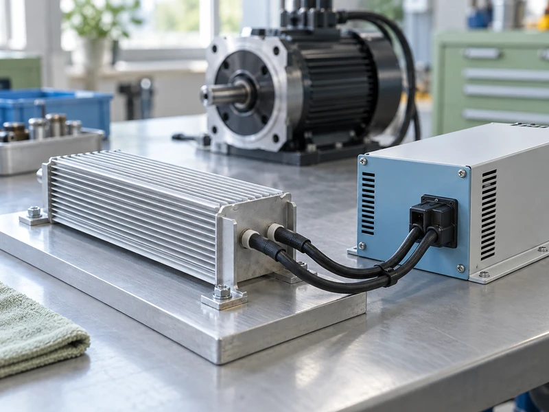
A chopper-controlled resistor is worth evaluating when repeated or sustained returned energy exceeds the available storage and the system does not need to recover it for reuse. The chopper connects the resistor as required to restrain bus voltage; the resistor converts the diverted energy into heat.
Select the resistance within the controller or chopper manufacturer’s permitted range. At the switching voltage, current is approximately V/R and resistor power is V²/R, so reducing resistance increases both. A resistor with an impressive wattage rating can still overload the switching device or fail under an unsuitable pulse.
- Check the permitted braking current and minimum resistance.
- Verify pulse energy against the actual pulse duration and repetition rate.
- Apply the resistor’s mounting and ambient-temperature derating.
- Coordinate activation voltage with normal supply variation and overvoltage thresholds.
- Document what happens if the resistor, switch, or temperature protection becomes unavailable.
Will a Battery or a Longer Stop Remove the Risk?
A battery is an energy destination only while its cells and battery management system permit the returning current. Verify charging limits at high state of charge, low temperature, and any other restricted operating condition. A battery that accepts regeneration during one test may reject it under another condition.
A longer deceleration period reduces average braking power for the same energy change, which may make absorption easier. It does not automatically reduce the total energy that must go somewhere. Likewise, sharing a DC bus helps only while another connected load is actually consuming enough power.
Separate voltage control from thermal control during troubleshooting. If the bus voltage is acceptable but the actuator heats excessively, review winding current, cooling, and holding time; GIAN’s discussion of BLDC motor overheating in robot actuators addresses that different operating constraint.
How Can You Compare Two Proposed Solutions?
Give both suppliers the same stopping sequence and ask them to identify the limiting condition. One proposal may depend on a longer stop, while another may preserve the original motion by adding a resistor and cooling capacity. Comparing purchase prices without these assumptions can conceal a change in machine performance.
Use a short acceptance matrix with three columns: operating condition, required result, and recorded evidence. For example, a maximum-speed stop should have a specified stopping-time limit, a permitted bus-voltage ceiling, and a saved measurement trace. A repeated-stop test should also establish that temperatures settle within the approved operating envelope.
Include a condition in which the preferred energy destination is unavailable, such as a battery refusing charge. Decide in advance whether the machine must stop through another validated method or inhibit that motion. A drive fault is a system response to evaluate, not proof that the requested stopping behavior has been achieved.
What Should You Send to the Motor Supplier?
Send a motion and energy specification alongside the usual torque and speed requirements. This makes it possible to assess the motor, transmission, controller, and power source as a connected system.
- Supply type, nominal voltage, maximum voltage, and documented ability to absorb power.
- Load inertia or mass, transmission ratio, maximum speed, and vertical travel.
- Shortest required stop time, reversal frequency, and simultaneous-axis behavior.
- Drive braking modes, fault thresholds, current limits, and relevant voltage traces.
- Available cooling, enclosure temperature, installation space, and stopping requirements during faults.
For a custom brushless DC motor project, ask GIAN to review those requirements before selecting the configuration. Confirm acceptance with the highest required speed and load, repeated stops, and the least favorable energy-absorption condition. Record both the maximum bus voltage and the stopping behavior, because avoiding an electrical trip is only part of a successful motion system.