
A drone BLDC motor usually overheats in a robot actuator not because BLDC technology is unsuitable for robotics, but because drone propulsion and robotic actuation place very different demands on the motor.
Drone motors are optimized around high speed, high power density, short peak loads, and strong airflow. Robot actuators often require low-speed torque, continuous holding current, frequent acceleration and reversal, and operation inside compact enclosed structures.
The main causes of overheating therefore tend to be connected:
high continuous torque → high current → I²R loss → limited cooling → rising winding temperature.
Gear ratio, motor Kv, gearbox friction, FOC tuning, duty cycle, and housing design can either improve or worsen that chain.
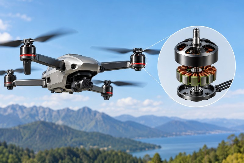
Drone Motors and Robot Actuators Have Different Duty Cycles
A drone motor normally operates at relatively high rotational speed. The propeller creates a continuous airflow around the motor, helping remove heat from the stator and housing.
A robot joint behaves differently.
Consider a robotic arm holding a 5 kg payload horizontally. The joint may barely rotate, but the motor must continuously generate torque to resist gravity. Electrically, the motor is working hard even though mechanically it appears almost stationary.
This difference is fundamental.
| Operating Condition | Drone Propulsion | Robot Actuator |
| Typical motor speed | High | Low to medium |
| Continuous airflow | Strong | Limited |
| Zero-speed torque | Rare | Common |
| Frequent reversals | Limited | Common |
| Continuous holding | Uncommon | Common |
| Enclosed installation | Rare | Common |
| Gear reduction | Usually none | Usually required |
A motor selected only from drone specifications such as maximum thrust, peak power, or maximum current can therefore be misleading when designing a robot actuator.
High Current at Low Speed Creates Copper Loss
Winding resistance is a major contributor to heat generation in BLDC motors. The basic relationship is:
Pcu = I²R
where:
- Pcu = copper loss
- I = winding current
- R = winding resistance
The important part is the square relationship.
Doubling motor current causes approximately four times greater copper loss. For example, assume the winding resistance is effectively 0.08 Ω under a given operating condition.
| Current | Approx. Copper Loss |
| 5 A | 2 W |
| 10 A | 8 W |
| 20 A | 32 W |
| 30 A | 72 W |
The exact calculation for a three-phase BLDC system depends on how resistance and phase current are defined, but the engineering lesson remains the same: continuous high current produces heat very quickly.
This becomes especially important in robot joints because torque is closely related to motor current.
When the actuator requires more torque, the controller increases current. If that torque must be maintained continuously, winding temperature continues to rise until heat generation and heat dissipation reach equilibrium—or until the motor exceeds its safe temperature.
Holding Torque Is Often the Worst Operating Point
A common mistake is assuming that a stationary motor should generate little heat because its mechanical output power is close to zero.
For an actuator, the opposite can happen.
Imagine a robot shoulder joint holding an arm horizontally. Motor speed may be:
0 RPM
but motor current could still be:
15–25 A
The motor is producing no meaningful mechanical power from rotation, but electrical losses remain.
At zero speed:
Mechanical output power ≈ 0
while:
Copper loss = I²R
still exists.
This makes prolonged holding one of the most demanding thermal conditions for many robot actuators.
If the robot spends significant time maintaining position against gravity, motor sizing should therefore be based on continuous torque and thermal capacity, not only peak torque.
Drone Cooling Disappears Inside the Robot
Cooling is another major difference.
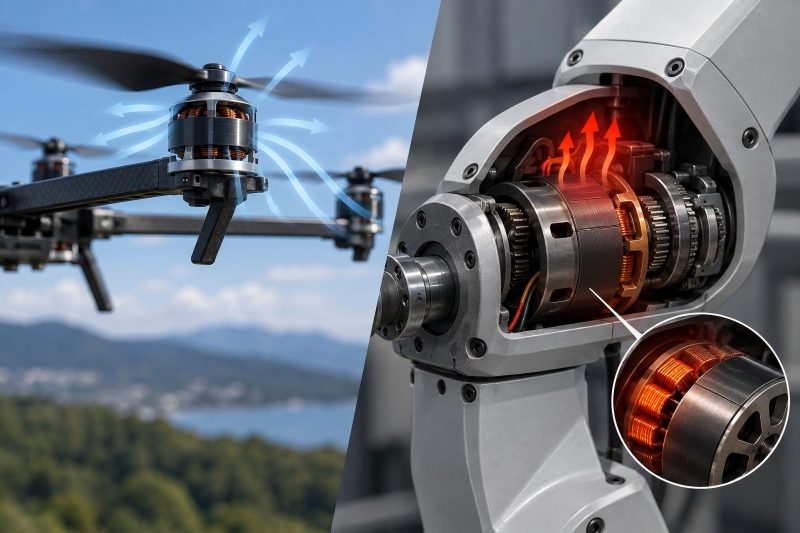
A drone motor operates directly in the air. Its rotating bell and propeller-induced airflow provide considerable convective cooling.
Install the same motor inside an actuator housing and that advantage may disappear.
The motor may now be surrounded by:
- gearbox components,
- structural aluminum,
- wiring,
- bearings,
- seals,
- covers,
Air circulation becomes weak, and heat can become trapped inside the actuator.
This means the same motor operating at the same current can reach very different temperatures depending on how it is installed.
A motor tested on an open bench is therefore not thermally equivalent to a motor installed inside a compact robot joint.
Gear Ratio Can Indirectly Cause Motor Overheating
The gearbox does more than increase output torque. It determines the operating point of the motor.
In simplified form:
Toutput ≈ Tmotor × N × η
where:
- Toutput = actuator output torque
- Tmotor = motor torque
- N = gear reduction ratio
- η = gearbox efficiency
Suppose a robot joint requires 30 Nm.
With a 10:1 reduction and 80% efficiency:
Tmotor ≈ 30 / (10 × 0.8) = 3.75 Nm
With a 30:1 reduction at the same efficiency:
Tmotor ≈ 1.25 Nm
The higher reduction can substantially reduce the torque and current required from the motor.
But simply increasing the reduction ratio is not always the answer. Higher ratios can reduce actuator speed, increase reflected friction, affect backdrivability, and introduce additional gearbox losses.
The correct ratio should place the motor in a practical torque-speed region rather than forcing it to operate continuously near its current limit.
Peak Torque and Continuous Torque Are Not the Same
Drone motors are often advertised using impressive peak values.
For robotic actuators, peak capability matters, but continuous capability matters more.
A motor may tolerate 40 A for several seconds during acceleration without damage. It cannot sustain 40 A continuously.
Robot motion often contains both short-term and long-term loads:
| Robot Condition | Torque Demand | Duration |
| Rapid acceleration | High | Short |
| Normal movement | Medium | Repeated |
| Holding against gravity | Medium/high | Long |
| Collision or jam | Very high | Short |
| Idle unloaded | Low | Long |
The thermal design should consider the complete duty cycle.
A useful way to evaluate this is RMS current:
Irms = √[(I₁²t₁ + I₂²t₂ + …)/(t₁ + t₂ + …)]
Because copper loss depends on current squared, RMS current gives a much better indication of thermal loading than average current.
Choosing the Wrong Motor Kv for the Application
Drone motors commonly have relatively high Kv because they are designed for high-speed operation.
Kv describes approximately how much no-load speed the motor produces per volt:
RPM ≈ Kv × Voltage
Torque constant is inversely related to Kv.
In SI units, a useful approximation is:
Kt ≈ 9.55 / Kv
when Kv is expressed in RPM/V and Kt in Nm/A.
A 1000 Kv motor therefore has approximately:
Kt ≈ 0.00955 Nm/A
A 100 Kv motor has approximately:
Kt ≈ 0.0955 Nm/A
The lower-Kv motor can theoretically generate much more torque per ampere.
This is one reason a high-Kv drone motor may struggle thermally in a slow robot actuator. It can generate the required torque, but doing so may require substantial current.
A gearbox can compensate by increasing reduction, but that introduces another design tradeoff.
For actuator applications, Kv should therefore be selected together with bus voltage, gearbox ratio, required joint speed, and continuous joint torque.
Gearbox Inefficiency Raises Motor Torque Demand
A planetary gearbox may have relatively high efficiency, while harmonic and cycloidal mechanisms can experience greater friction depending on design, preload, lubrication, ratio, and operating condition.
If the gearbox requires additional torque simply to overcome internal friction, the motor must supply that torque continuously.
For example:
Required motor torque = load torque + acceleration torque + drivetrain losses
In practice, gearbox losses can become particularly noticeable during slow motion.
If an actuator becomes significantly hotter after changing gearbox preload, lubrication, bearings, or assembly tolerances, the motor may not actually be the root cause.
The motor may simply be converting drivetrain friction into heat.
Poor FOC Tuning Can Produce Heat Without Useful Torque
Motor hardware is only half of the actuator.
Controller configuration also affects temperature.
A poorly tuned field-oriented control system may generate unnecessary current because of:
- incorrect motor parameters,
- inaccurate electrical angle,
- encoder offset error,
- poor current-loop tuning,
- incorrect pole-pair configuration,
- excessive current commands,
- current sensor calibration errors.
In a well-controlled PMSM/BLDC actuator, current should be directed efficiently toward torque production.
If electrical angle is incorrect, part of the current may contribute little useful torque while still generating I²R losses.
A practical warning sign is a motor that becomes hot even when mechanical output torque appears lower than expected.
In that situation, checking the controller and encoder alignment should come before replacing the motor.
Repeated Acceleration and Reversal Add Thermal Load
Robots rarely rotate continuously in one direction.
A typical joint may repeatedly:
Accelerate → Decelerate → Stop → Reverse → Accelerate
Every acceleration requires torque. With high reflected inertia, the required torque can become substantial:
T = Jα
where:
- T = acceleration torque
- J = effective inertia
- α = angular acceleration
Aggressive motion profiles can therefore generate large current peaks.
A motor may look adequately sized based on static joint torque but still overheat during repeated high-speed cycles.
This is why actuator design should include both static torque analysis and dynamic motion analysis.

Heat Cannot Escape Through the Mechanical Structure
An actuator housing can either trap heat or become an effective heat sink.
A motor tightly coupled to an aluminum housing can transfer heat through conduction. The robot structure itself can then provide a large thermal path.
A motor suspended inside a housing with only small mounting contact areas may have poor conduction.
Useful thermal improvements can include:
- increasing motor-to-housing contact area,
- using aluminum motor mounts,
- reducing unnecessary thermal interfaces,
- adding thermally conductive interface material where appropriate,
- providing ventilation when contamination requirements allow,
- separating motor heat from sensitive electronics.
In compact actuators, thermal architecture should be designed together with the mechanical architecture.
How to Diagnose an Overheating Drone Motor
Do not start by simply installing a larger motor.
Find the root cause of overheating before making adjustments.
| Observation | Likely Direction to Investigate |
| Hot mainly during holding | Continuous current / insufficient reduction |
| Hot during rapid movement | Acceleration torque / current peaks |
| Hot even with little load | FOC tuning / friction / alignment |
| Cool outside housing, hot inside | Poor thermal dissipation |
| Motor and gearbox both hot | Gearbox friction |
| ESC/controller also very hot | Current level / switching / control issue |
| Temperature rises after assembly | Bearing preload / mechanical interference |
Measure motor current, winding or stator temperature, joint torque, motor speed, gearbox temperature, and controller temperature during an actual robot cycle.
This usually tells much more than checking the motor’s maximum current specification.
A Better Motor Selection Approach
For a robot actuator, begin at the joint rather than at the motor.
Define:
- continuous joint torque,
- peak joint torque,
- maximum joint speed,
- acceleration requirement,
- duty cycle,
- holding time,
- available bus voltage,
- gearbox efficiency,
- target reduction ratio,
- allowable motor temperature.
Then work backward through the drivetrain.
If the joint requires continuous torque Tjoint, the approximate motor requirement becomes:
Tmotor = Tjoint / (N × η)
From the motor torque constant:
Imotor ≈ Tmotor / Kt
This current can then be used to estimate winding losses and thermal loading.
The result may reveal that a motor capable of excellent drone performance is poorly matched to the actuator.