
A BLDC motor system should have a defined response when its supply falls and later returns. The driver may disable its outputs, the controller may reset, and a stored motion command may survive in a different part of the system. Brownout recovery testing establishes how those states are reconciled before motion resumes.
Specify the restart policy as part of the machine’s operating sequence. A design may permit automatic resumption after defined checks, or it may require the operator to issue a new command. Resolve that choice before approving the driver and prototype.
What Counts as a Brownout in This System?
Define the voltage disturbance at the equipment terminals, including its depth, duration and recovery shape. A shallow dip lasting milliseconds can produce a different response from a slow collapse or complete power removal. The supply’s nominal voltage does not describe these events.
Identify every relevant power domain. Motor power, controller logic, sensors and communication interfaces may use separate regulators or separate supplies. One domain can remain active while another resets, leaving the system in a partially powered condition.
Start the discussion with the chosen brushless DC motor and the actual load. A freely rotating demonstration motor does not represent a mechanism that retains energy, carries a standing load or needs a known position before moving again.
Then document the undervoltage behavior of the BLDC motor driver. Ask for the relevant thresholds, hysteresis, fault indication and reset conditions for the exact revision. Those features should come from the driver documentation or measured evidence, not assumptions based on another model.
Which States Can Become Inconsistent?
Consider a controller that continues sending a speed command while the motor power stage is disabled. When the supply recovers, the driver might accept that existing command immediately, or it might remain faulted until reset. Either behavior can surprise an integrator who tested only complete power cycling.
A different case occurs when the controller resets but the motor driver remains powered. Output pins can change state during boot, communication may be temporarily unavailable, and the controller may lose its previous operating context. The startup sequence needs to account for that interval.
Position information also deserves separate treatment. An incremental count may be lost when its controller resets, while a mechanical axis remains at an arbitrary location. Restoring electrical power does not by itself restore the validity of the machine’s position reference.
NASA’s account of Ingenuity’s winter brownouts describes loss of onboard state, including clock reset, after power depletion. That is a different application, but it illustrates why recovery must address retained information as well as voltage restoration; it is not a BLDC qualification standard.
How Should the Intended Recovery Sequence Be Written?
Write the required sequence in terms of observable states. For example, the system detects a supply fault, inhibits motion, reports the event, waits for stable power and accepts a new enable only after the required checks. The exact sequence should follow the machine’s operating requirements.
Separate fault clearance from permission to move. A voltage fault disappearing can establish that the electrical condition has recovered without establishing that the previous command remains appropriate. The controller should have a defined rule for stale commands.
Gian’s controller and driver comparison helps distinguish where these decisions belong. Specify which component detects the disturbance, which component holds the fault and which component authorizes the next motion.
Also define how an operator or supervisory system sees the event. A fault that clears too quickly to be observed may leave no useful explanation for an interrupted cycle. Event retention and communication behavior should be considered part of the recovery interface.
Which Disturbances Should the Test Include?
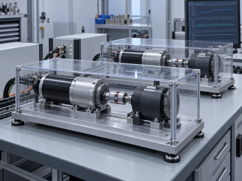
Choose a focused set of disturbances based on the intended supply environment and the documented thresholds. Include conditions just above and below relevant transition points, along with representative longer interruptions. Do not invent a universal voltage-dip profile and call it suitable for every machine.
The test equipment must be appropriate for controlled supply variation and for the energy returned by the connected system. A supply that cannot handle the circuit’s behavior can distort the result or create a different fault. Establish a reviewed bench method before applying disturbances to a loaded axis.
| Disturbance Case | Behavior to Observe |
| Brief motor-supply dip | Driver inhibition, fault reporting and command retention |
| Logic supply interruption | Controller boot state and output behavior |
| Slow voltage recovery | Repeated threshold crossings or unstable enabling |
| Repeated dips | Fault accumulation and recovery consistency |
| Recovery during an active command | Whether a fresh command is required before motion |
Repeat relevant cases at standstill and during representative motion. A moving load can retain mechanical energy after the output stage disables. Observe what the mechanism actually does rather than treating an electrical fault bit as a complete description of the event.
Include the allowed load and ambient conditions that could affect the result. A test with an unloaded motor at room temperature may establish basic logic behavior, but it does not cover every operating condition of the machine. State the scope of the evidence clearly.
What Should Be Captured During Each Event?
Capture supply voltage at the driver terminals, relevant logic voltage, enable or command signals, fault outputs and a measure of motion. Use synchronized records where possible so the order of events can be established. Separate screenshots without a shared time reference can make a brief event difficult to reconstruct.
Record the disturbance source settings and the actual measured waveform. Cable impedance and local capacitance can make the voltage at the driver differ from the programmed source profile. The equipment-terminal waveform is the more useful description of what the system experienced.
Log firmware, driver configuration and boot timing. A software revision can change recovery behavior even when the power hardware is unchanged. Include communication timeout settings and any automatic retry function that participates in the sequence.
Gian’s article on BLDC driver failure causes provides broader troubleshooting context. Brownout recovery testing should isolate the supply disturbance sufficiently to distinguish an intended protective response from an unrelated wiring or thermal problem.
How Can Repeated Restart Attempts Be Prevented?
A system can oscillate between enable and undervoltage if starting the load pulls the supply down again. The resulting repeated attempts may appear as twitching, cycling fault indicators or intermittent communication. A single successful restart does not rule out this behavior near the operating boundary.
Define how the controller responds to unsuccessful attempts. Depending on the application, it may need a retained fault, a limited retry policy or a requirement for a new command. The chosen rule should be visible in the test record and verified under the relevant disturbance.
Check the interaction with the upstream power source. Current limiting, wiring voltage drop and other loads on a shared bus can all influence recovery. Testing the motor drive alone may miss a system-level supply interaction.
Do not confuse an undervoltage event with a regenerative overvoltage event. Gian’s discussion of BLDC regenerative braking overvoltage addresses the opposite direction of bus-voltage excursion. A complete design may need both assessments, but their triggers and remedies should remain distinct.
What Evidence Is Needed Before Release?
For each test case, record the expected response, observed response and pass criterion. Useful criteria describe motion permission, fault visibility, retained state and the conditions required for restart. A general note saying that the motor recovered is too ambiguous for later comparison.
Retain at least the relevant waveforms, event logs and configuration identifiers. If an unexpected movement occurs, preserve the sequence before changing settings. The trace may reveal an interaction that is difficult to reproduce after several parameters are changed together.
Send Gian the supply architecture, disturbance envelope, load description and required restart policy when reviewing a motor and driver combination. This allows the discussion to focus on the actual machine interface rather than only the motor’s nominal voltage.
Revisit the assessment after changes to the supply, controller firmware, driver revision or recovery logic. The released result should state precisely how the tested configuration behaves when power becomes inadequate and what must happen before the machine is allowed to move again.