
Before drive matching, buyers need inrunner BLDC motor inductance data defined by winding connection, measurement method, rotor position, current, and temperature. One nominal value cannot describe every operating condition or prove compatibility.
Gian Transmission offers customized winding, voltage, and interface options; drive selection still requires application-specific electrical data and verification.
Confirm the Winding Connection and Inductance Convention
Buyers reviewing custom inrunner BLDC motor configurations should also define the broader brushless DC motor design requirements. Product information provides context, but it does not replace a motor-specific inductance record.
Phase Inductance vs. Line-to-Line Inductance
Phase inductance describes one phase under a defined electrical and magnetic condition. Line-to-line inductance is measured between two motor terminals and reflects the connected winding network.
The values are not automatically interchangeable. A terminal measurement can include more than one phase and the magnetic coupling between them.
Buyers should establish which terminals were connected, whether unused terminals were open or connected, and whether the motor retained its normal internal connection. The test circuit determines what the displayed number represents.
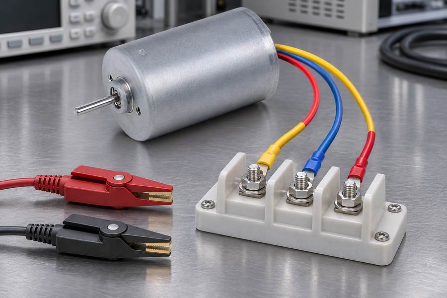
A phase value can be measured directly when the winding provides access to the relevant phase and reference point.
If the neutral is inaccessible, a reported phase value may be derived from a terminal measurement and must include its model assumptions.
Star (Wye) vs. Delta Winding Configuration
In a star-connected winding, each phase joins at a common neutral point. In a delta-connected winding, the phase windings form a closed loop.
The same instrument connection does not necessarily represent the same phase circuit in both arrangements. A conversion based on a balanced star winding must not be applied automatically to a delta winding.
Conversion also depends on phase-inductance definition, winding polarity, mutual coupling, and the condition of unused terminals. Without these details, a calculated value may describe the wrong electrical quantity.
Request the winding diagram, not merely a label such as three-phase or internally connected. It should identify terminals, connection points, parallel paths, and any accessible neutral.
Self-Inductance, Mutual Inductance, and Winding Documentation
Self-inductance describes flux linkage in a winding caused by current in that same winding. Mutual inductance describes flux linkage induced in one winding by current in another.
A multiphase terminal response includes both effects. The sign and contribution of mutual terms depend on winding reference directions and the current convention used in the model.
A supplier’s phase value, a buyer’s terminal measurement, and a drive’s equivalent parameter may therefore differ without indicating a defect. They may represent different definitions or connection conditions.
| Item | What it describes | What buyers should confirm |
| Phase inductance | Inductance assigned to one phase | Phase reference and neutral access |
| Line-to-line inductance | Terminal response between two phases | Test terminals and unused-terminal condition |
| Self-inductance | Flux linkage caused by current in the same winding | Winding and current reference |
| Mutual inductance | Coupling between different phase windings | Polarity and sign convention |
| Equivalent inductance | Model value for a defined circuit | Topology and conversion assumptions |
Do not accept a conversion without its assumptions. Ask whether the figure was measured directly, calculated from another quantity, or extracted from a motor model.
- Connection: Record star or delta topology and identify all motor terminals.
- Measurement path: State the instrument terminals and condition of every unused terminal.
- Winding layout: Record parallel paths and accessible neutral connections.
- Inductance definition: Label the result as phase, line-to-line, self, mutual, or equivalent inductance.
Verify the Inductance Measurement Method, Frequency, and Amplitude
LCR Meter and Impedance-Based Measurement
An LCR meter applies a small alternating test signal and evaluates the resulting voltage-current relationship. Its inductance reading is derived from impedance under the selected instrument model.
The equivalent-circuit mode matters. Series-equivalent and parallel-equivalent readings can differ, particularly when winding resistance and losses are significant relative to measured reactance.
Long leads, loose clips, contact resistance, and uncompensated fixtures can distort low-inductance measurements. Retain the instrument settings and fixture configuration when recording the result.
Establish whether the motor was disconnected from the drive and tested directly at its terminals. Measurements through cables, filters, or connected electronics may include elements outside the motor winding.
Why Measurement Frequency Changes the Reported Value
A practical motor measurement may not produce one frequency-independent inductance value. Core losses, eddy-current effects, winding proximity effects, parasitic capacitance, and the instrument’s model can influence the result.
The reported equivalent inductance may therefore change with test frequency. The direction and size depend on construction and test range; buyers should not assume a universal correction.
Measurements taken at different frequencies should not be compared unless the test frequency and measurement convention are stated.
Do not substitute the drive’s PWM frequency automatically for the LCR test frequency. Switching waveforms, current bias, back-EMF, and rotor movement are not reproduced by a simple small-signal test.
Specify the AC Test Amplitude
Record the AC test amplitude as a voltage or current level, together with the instrument’s test mode. It defines the size of the probing signal.
A small AC signal generally characterizes the local response around the existing magnetic operating point. Without DC bias, it does not show how inductance changes under substantial motor current.
Do not confuse AC test amplitude with DC bias current. The AC signal is the measurement perturbation; DC bias establishes the magnetic operating point around which that perturbation is evaluated.
A reproducible record includes instrument type, series or parallel mode, frequency, AC amplitude, DC bias if used, fixture compensation, and terminal connection.
An LCR reading remains a defined small-signal result, not a complete map over speed, torque, current, and rotor position.
Identify Rotor Position and the d/q-Axis Inductance
Why Rotor Position Influences Inductance
The rotor changes the magnetic path seen by the stator as it turns. Where the rotor has magnetic saliency, reluctance differs along rotor axes and measured inductance can vary with angular position.
A single locked-rotor reading may describe only one position. It should not be presented as position-independent unless the design and measurement evidence support that interpretation.
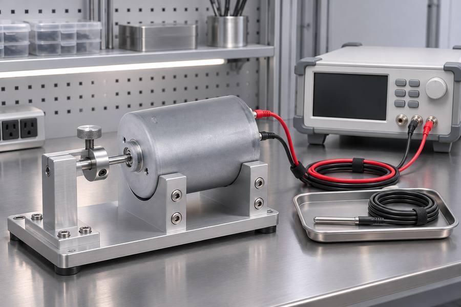
The angular reference must be explicit. Mechanical angle describes physical rotation; electrical angle accounts for pole-pair count and repeats over each electrical cycle.
For a motor with multiple pole pairs, a given mechanical movement corresponds to a larger electrical-angle change. Record the pole-pair count and the chosen zero reference.
Understand d-Axis and q-Axis Inductance
In a rotor-oriented model, the d-axis aligns with the permanent-magnet flux reference. The q-axis is displaced by 90 electrical degrees from the d-axis.
Direct-axis inductance, Ld, and quadrature-axis inductance, Lq, describe winding response along these axes. They are model parameters, not labels for measurements taken at arbitrary mechanical positions.
In a motor with appreciable saliency, Ld and Lq may differ. In a design with little saliency, they may be closer, but buyers should use documented data rather than assume equality.
The distinction matters when a drive uses rotor-oriented current control. A single scalar value may suit a simplified model, but cannot represent axis-dependent behavior when that difference affects control calculations.
Identify how Ld and Lq were obtained. Locked-rotor tests, flux-linkage characterization, and parameter identification can produce results that are not directly comparable without consistent conventions.
What Rotor Position Information Should Buyers Request?
- Angular reference: Identify the electrical zero position and its relationship to the rotor.
- Pole-pair count: State the count used to convert mechanical angle into electrical angle.
- Test positions: Record positions covered and whether the rotor was locked.
- Axis convention: Define d-axis and q-axis orientation and sign convention.
- Reported parameters: Identify whether results are terminal inductance or separate Ld and Lq values.
If inductance changes with rotor angle, request enough position coverage to show variation relevant to the intended model. Do not turn one reading into a full angular map by assumption.
Evaluate Current Bias, Magnetic Saturation, and Inductance Type
How Current Bias Influences Motor Inductance
Stator current establishes a magnetic operating point. As current increases, parts of the magnetic circuit may approach saturation, changing the relationship between additional current and flux linkage.
Inductance measured with no DC bias may therefore differ from the value around a loaded operating point. The difference depends on magnetic design, current direction, rotor position, and the inductance definition.
A useful characterization separates the small AC perturbation from the DC bias. Bias establishes the operating point; the AC signal measures the local response around it.
A zero-bias LCR result is a reference, not a guaranteed value at rated or peak current. Request operating-current data when the drive model depends on saturation.
Incremental Inductance vs. Apparent Inductance
Incremental inductance describes the local slope of flux linkage against current around a specified operating point. In a simplified single-axis description, it is the derivative of flux linkage with respect to a small current change.
Apparent, or secant, inductance describes a flux-linkage relationship relative to a stated reference. The reference matters because permanent magnets contribute flux linkage even when stator current is zero.
Dividing total flux linkage by current without accounting for permanent-magnet flux offset can produce a misleading result. The supplier should state how magnet-related flux and the reference condition are handled.
The two definitions can differ when the magnetic circuit is nonlinear. Neither should be reported simply as motor inductance without a label, current condition, and calculation convention.
The required definition depends on the motor model and control method. Specify the quantity used by the intended model rather than demanding one universal inductance label.
Current-Dependent Inductance and Cross-Saturation
In a rotor-oriented model, d-axis and q-axis currents can influence the magnetic state together. A change in one current component may alter the incremental response associated with the other axis.
This interaction is called cross-saturation. Where it is material, fixed Ld and Lq values may not represent the full operating region.
Ask whether data are measured at zero bias, selected current points, or across a current-dependent map. Identify whether values are incremental or apparent and whether cross-coupling terms are included.
A current-dependent map is relevant when the intended operating range reaches conditions where saturation or axis interaction affects control accuracy. Request the level of detail needed by the actual motor model.
Check Temperature Conditions, Inductance Tolerances, and Production Variation
Understand the Influence of Temperature on Inductance
Temperature affects several parts of motor electrical and magnetic behavior. Winding resistance changes with conductor temperature, while magnetic materials and permanent magnets can also respond to temperature.
A measured impedance change does not automatically mean inductance changed by the same proportion. Resistance, magnetic properties, and instrument modeling can all influence the displayed result.
Record winding temperature and, where relevant, rotor or magnetic-component temperature. Ambient temperature alone may not describe the motor after operation or thermal stabilization.
Room-temperature data are useful for incoming comparison, but should not be represented as hot-condition parameters. If the drive model needs operating-temperature values, define how they will be measured or established.
Evaluate Inductance Tolerances and Manufacturing Variation
Inductance can vary between motors because winding placement, coil geometry, air gap, magnetic material properties, and assembly dimensions vary in production.
How strongly winding placement, coil geometry, air-gap dimensions, magnetic material properties, and assembly tolerances affect measured inductance varies with the motor’s magnetic circuit and construction.
Separate the nominal value, permitted production range, and measurement uncertainty. They answer different questions and should not be combined into one unexplained tolerance.
Measurement uncertainty describes confidence in a result under the stated procedure. Production variation describes differences among physical motors measured correctly using that same procedure.
A prototype result does not establish production distribution. For repeat orders, agree on sampling, acceptance limits, and treatment of results near those limits.
Avoid inventing a universal inductance tolerance. Set the acceptable range using motor design, drive sensitivity, application requirements, and demonstrated manufacturing capability.
Establish Repeatable Inductance Testing Conditions
Repeatability depends on more than the instrument. Terminal contact, fixture layout, rotor angle, frequency, signal amplitude, DC bias, and temperature should remain consistent.
If measurements disagree, compare definitions and setups first. Repeating a test without correcting a different terminal connection or rotor reference may reproduce the discrepancy rather than identify its cause.
Keep motor identification and production batch with every result. This distinguishes a unit-specific deviation from a test-process change or a broader manufacturing trend.
- Test setup: Preserve connection diagrams, instrument settings, and fixture-compensation records.
- Motor condition: Record winding temperature, rotor position, and external electrical connections.
- Traceability: Link each reading to a motor or batch identifier and test date.
- Acceptance basis: Compare results with an agreed range using the same convention.
Apply Inductance Data to PWM, Current Control, and Drive Matching
Understand the Relationship Between Inductance and PWM Current Ripple
Inductance opposes rapid changes in winding current. For a given net voltage across the inductive element, greater applicable inductance produces a smaller current change over the same interval.
The following relationship is illustrative:
Δi ≈ (VL × Δt) / L
Here, Δi is current change, VL is the approximately constant net voltage acting across the inductive element, Δt is the interval, and L is inductance at that operating point.
This approximation assumes voltage and inductance remain nearly constant during the interval. In a motor phase model, VL is the net voltage after accounting for resistive drop and back-EMF, not automatically the full DC bus voltage.
Actual PWM ripple depends on switching state, DC bus voltage, modulation, duty interval, back-EMF, current, rotor position, and winding connection. If inductance changes with current, the relevant incremental value may be more useful than a zero-bias nominal reading.
This is not a complete ripple prediction or universal switching-frequency rule; estimation requires actual drive voltage states and motor operating conditions.
Relate Inductance to Current-Loop Configuration and Parameter Identification
Inductance and resistance influence how quickly winding current responds to applied voltage. In a simplified series RL circuit, the time constant is τ = L/R, provided L and R refer to the same equivalent circuit and condition.
That expression is a first-order reference, not a complete motor-control model. A driven motor also involves back-EMF, rotor position, inverter voltage limits, sampling and computation delays, and the selected control structure.
Current-loop tuning cannot be selected from inductance alone. The model needs consistent resistance and inductance definitions, plus the voltage range, current range, and timing constraints relevant to the application.
Parameter identification may also use flux linkage, pole-pair count, and rotor-oriented Ld/Lq values. These parameters need compatible axis conventions, temperature conditions, and current definitions; mixing line-to-line data with a phase-based model can invalidate the result.
Distinguish measured motor parameters from values estimated by a controller during operation. An estimate depends on its identification procedure and operating point, so it should not silently replace agreed supplier data.
Prepare the Motor Inductance Data Required Before Drive Matching
The procurement record must state the electrical quantity, test condition, connection convention, and traceable motor identity.
| Data category | Information to request |
| Winding configuration | Star or delta, phase terminals, parallel paths |
| Inductance definition | Phase, line-to-line, self, mutual, Ld, or Lq |
| Measurement method | Instrument method and series or parallel convention |
| Test conditions | Frequency, AC amplitude, fixture compensation |
| Rotor position | Angular reference, pole-pair count, test positions |
| Current conditions | DC bias, operating-current points, saturation data |
| Inductance type | Incremental or apparent, with calculation convention |
| Temperature | Winding and relevant magnetic-component temperatures |
| Production variation | Nominal value, agreed range, sample variation |
| Drive requirements | DC bus range, current range, control method, PWM conditions |
Before approval, compare the motor record with parameter fields required by the intended drive model. Confirm that phase and line-to-line quantities, axis references, and inductance definitions are consistent.
If a required value is unavailable, mark it unverified rather than deriving it from an unrelated measurement. Request clarification or an agreed characterization method before using it for controller configuration.
For acceptance, agree in advance on connection, instrument convention, frequency, amplitude, rotor position, temperature, and any DC bias. Define the nominal value and permitted range after considering drive sensitivity and demonstrated production capability.
Retain original readings, calculated values, conversion assumptions, and approval revision together. Any change to winding connection, rotor construction, or agreed test method should trigger review before drive settings are released.