
Before repeated reversals, check shaft fit, torque-transmitting features, fastener locking, axial restraint, rotor-bell attachment, bearing endplay, and harness retention. Compare measured runout, endplay, and angular slip before and after controlled, guarded reversal operation.
Gian Transmission outrunner configurations must be evaluated against actual drawings because shaft-mounted does not establish which shaft rotates.
How Should You Identify the Motor’s Actual Mounting and Retention Interfaces?
Confirm Stationary and Rotating Components from the Assembly Drawing
A shaft-mounted outrunner motor must be evaluated according to its actual mechanical arrangement. The mounting description alone cannot establish whether the shaft rotates or supports stationary components.
Start with the approved assembly drawing and identify the stator support, rotor bell, shaft, bearings, housing interfaces, and connection to the driven equipment.
In some arrangements, the shaft transmits rotation directly to the load. Other configurations may use a stationary shaft supporting a rotating assembly through bearings.
The stationary support must resist the reaction torque generated during operation. Its attachment to the machine frame requires verification alongside the rotating transmission interface.
For outrunner brushless DC motor configurations, engineers should identify these interfaces before specifying retention checks or interpreting movement observed during testing.
Separate Torque Transmission from Axial Retention
Torque transmission prevents unacceptable relative angular movement between connected components. Axial retention prevents unwanted displacement along the relevant shaft or bearing axis.
These functions may share mechanical elements, but they represent different load requirements. A connection transmitting sufficient torque does not automatically provide adequate axial restraint.
A clamped interface, for example, may depend on contact pressure for torque transmission. Its axial holding capability must also be established if the design relies on that interface.
Identify the intended load path for each function, including contact surfaces, fasteners, bearings, shoulders, and any specified retaining features.
The resulting interface diagram should show where bidirectional torque enters and leaves each connection and how axial forces reach the supporting structure.
What Reversal Loads Must the Retention System Withstand?
Calculate Signed Reversal Torque
Repeated reversals impose changing torque directions on shaft connections. Retention selection must therefore consider acceleration, deceleration, operating loads, and transient mechanical behavior.
For a simplified rigid drivetrain, required drive torque at a defined reference shaft can be expressed using the following signed relationship.
T_required = J_equivalent × α + T_load
Here, J_equivalent represents inertia referred to the selected shaft, α represents signed angular acceleration, and T_load represents the signed torque required to oppose external loading.
Choose one positive rotation direction and apply the same sign convention throughout. Reversing acceleration can change the required torque direction even while rotation remains forward.
Include relevant rotor and reflected load inertia without counting individual components twice. Gear ratios and transmission arrangements must be accounted for when referring quantities to one shaft.
Where friction, transmission losses, or other significant torques are excluded from T_load, include them separately with appropriate signs and operating assumptions.
The calculation establishes a useful torque demand for the defined motion model. It does not automatically capture every short-duration mechanical impact occurring during reversal.
Evaluate Transient and Cyclic Loading
Backlash can allow connected components to move relative to one another before opposite contact surfaces engage. The resulting impact may exceed the commanded motor torque.
Impact severity depends on relative speed, rotational inertia, contact stiffness, damping, and available clearance. Controller torque limiting alone cannot establish the maximum contact force.
Repeated changes in torque direction can also produce cyclic interface movement, fretting, and progressive loss of contact integrity when a connection is inadequately designed.
Regenerative operation requires consideration because braking torque and controller transitions influence deceleration behavior. Electrical operating limits must be reviewed alongside mechanical load conditions.
Define representative reversal speed, acceleration, external load, backlash condition, and operating frequency. Use these conditions to establish the approved validation envelope.
Which Shaft Fit and Fastener Retention Checks Are Necessary?
Inspect Torque-Transmitting Interfaces
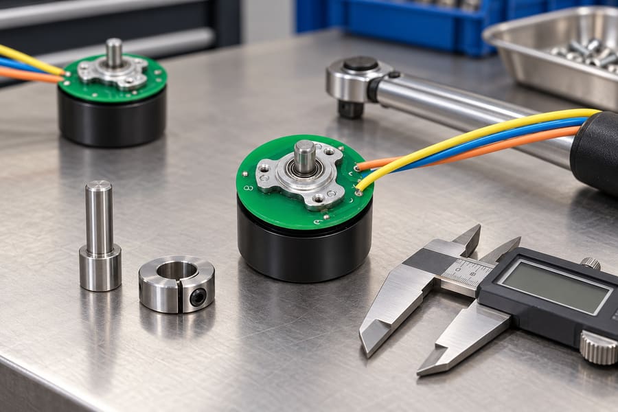
Shaft and collar samples illustrate fit and clamping checks where those features are specified. They are separate examples, not evidence of the pictured motor’s internal retention design or approved tightening settings.
Begin by examining the shaft diameter, mating bore, engagement length, surface condition, and specified fit. Compare actual dimensions with controlled interface drawings.
Fit quality influences contact distribution and relative movement under changing torque. Excessive clearance or insufficient engagement may increase local loading and interface wear.
Inspect keys, keyways, flats, split clamps, or other torque-transmitting features only when they form part of the approved design.
For keyed connections, examine engagement and contact condition. For clamped connections, verify the specified mating geometry, contact arrangement, and approved tightening procedure.
Fretting debris, polished contact bands, localized indentation, or displaced reference marks can indicate interface movement. Such evidence requires investigation rather than automatic acceptance.
Do not assume that a tight hand fit establishes adequate torque retention. Inspection must address the complete assembled interface under its intended loading conditions.
Verify Fastener Installation and Locking
Fasteners may provide clamping force, secure support structures, or retain components axially. Identify their actual function before selecting the corresponding inspection method.
Confirm fastener grade where specified, thread engagement, mating surface condition, installation sequence, and the locking method approved for the particular assembly.
Preload depends on more than an indicated tightening torque. Thread friction, bearing-surface friction, lubrication, and assembly condition can significantly influence achieved clamping force.
Witness marks help reveal relative movement between marked components. However, unchanged marks cannot demonstrate that the original fastener preload remains adequate.
Use only design-approved tightening settings, locking compounds, or mechanical locking features. No universal torque or adhesive specification is suitable for every outrunner installation.
| Retention Interface | Inspection Requirement | Potential Reversal Failure | Verification Evidence |
| Shaft-to-bore fit | Measure fit, engagement, and contact condition. | Angular slip, fretting, or local deformation | Dimensional inspection and slip measurements |
| Key or flat, if specified | Check seating, engagement, and contact surfaces. | Backlash growth or local damage | Assembly inspection and contact evidence |
| Clamping connection | Verify geometry and approved installation conditions. | Loss of contact pressure or slip | Assembly records and retention testing |
| Threaded fasteners | Confirm engagement, installation, and locking. | Loosening during torque cycling | Installation records and condition inspection |
| Axial retaining features | Check designed engagement and load path. | Axial displacement or separation | Drawing review and endplay measurements |
| Rotor-bell attachment | Verify specified interface and attachment condition. | Relative movement or attachment damage | Approved inspection or qualification evidence |
How Should Axial Retention and Rotor-Bell Attachment Be Checked?
Verify the Designed Axial Load Path
Axial retention must be evaluated independently from torque transmission, even where one component performs both functions. Identify expected axial forces and their directions.
Depending on the design, axial restraint may involve shoulders, retaining rings, bearing arrangements, threaded components, clamping surfaces, or other specified mechanical features.
Check seating, engagement, contact condition, and permitted displacement for the features actually installed. A circlip should not be assumed present simply because the assembly contains a shaft.
Likewise, adequate retention does not necessarily require a second independent device. The requirement is a sufficiently capable, verified axial load path consistent with the approved design.
Evaluate axial loading during installation, operation, and reversals. Consider thermal expansion and bearing movement where these affect the position or loading of retained components.
Inspect Rotor-Bell-to-Shaft Retention
The rotor bell and shaft may be joined using different attachment arrangements. Their actual connection must be identified from drawings or approved technical documentation.
Inspect accessible interfaces for looseness, displacement, distortion, fretting, or contact damage. Avoid assuming that externally visible features fully describe the internal attachment.
A connection that remains secure during steady rotation may experience different stress conditions during abrupt reversals, especially when torsional oscillation or impact occurs.
Where an internal connection cannot be inspected without disassembly, request appropriate supplier-approved retention evidence rather than disturbing a sealed or otherwise restricted assembly.
Review Magnet and Bond Retention Where Relevant
Outrunner rotor construction may include magnets secured by bonding or other mechanical arrangements. Review the actual design to determine whether additional retention assessment is relevant.
Consider centrifugal loading, temperature exposure, repeated acceleration, and approved operating limits. Magnet retention requirements should reflect the applicable rotor construction and duty.
Visible damage, unusual noise, or changes in rotor behavior warrant investigation. These observations alone do not identify a particular internal bond or attachment failure.
Use approved inspection procedures and available qualification evidence. Do not remove magnets, disturb bonded structures, or disassemble the rotor without an authorized service procedure.
What Bearing, Alignment, and Harness Checks Are Required?
Evaluate Bearing Loads and Shaft Movement
Bearings influence shaft positioning, rotor alignment, and movement under reversing loads. Their condition must be evaluated together with the surrounding mechanical interfaces.
Determine radial loads, axial loads, overhung moments, and operating speeds using the actual installation geometry. Consider coupling alignment and external support arrangements.
A load applied beyond the bearing support can create a bending moment even when the transmitted torque remains within the approved operating range.
Measure shaft or rotor runout at clearly defined locations using suitable inspection equipment. Record fixture condition, measurement direction, and component rotational reference.
Axial endplay should also be measured according to the approved procedure. Excessive movement may indicate bearing wear, incorrect assembly, or problems elsewhere in the axial load path.
Compare measurements with design-specific acceptance requirements rather than applying an arbitrary universal runout or endplay threshold.
Verify Harness Restraint and Clearance
Electrical harnesses connected to stationary motor components must remain clear of the rotating bell and any other moving shaft or coupling surfaces.
Confirm routing, strain relief, connector engagement, and protection against abrasion. Allow for vibration, thermal movement, and practical assembly tolerances.
Any necessary service loop must remain restrained outside the rotating swept envelope. Reversal testing should not permit wiring to contact moving components.
Check the harness after assembly and cover installation because closure can displace wiring. Electrical connections should not carry unintended mechanical restraint loads.
How Should Reversal Testing Verify Retention Performance?
Establish Baseline Measurements
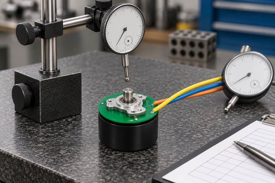
Record measurement locations and references before reversal testing. This stationary inspection preparation illustrates runout and endplay planning; the gauges do not display measured product results or acceptance limits.
Before testing, record assembly identification, interface configuration, fastener installation records, and the condition of accessible retention features.
Measure initial shaft and rotor runout, axial endplay, and relative angular position at specified reference locations. Use consistent equipment and measurement methods.
Where practical, establish angular references across the actual torque-transmitting interface, such as between the shaft and its connected driven component.
For internal interfaces that cannot be measured directly, identify alternative approved verification evidence and clearly document the resulting measurement limitations.
Record measurement uncertainty and repeatability. Small observed changes should not be classified as interface slip without considering instrument resolution and fixture movement.
Conduct Guarded Representative Reversal Tests
Testing must use approved guarding, fixtures, connected loads, and controller settings. Personnel must remain protected from exposed rotation and possible component release.
Begin with controlled motion to confirm direction, clearance, and normal mechanical behavior. Increase operating demands only within the approved test procedure.
Representative conditions should include relevant acceleration, deceleration, reversal frequency, load variation, and expected thermal operating states.
Monitor vibration, temperature, abnormal noise, axial movement, and any available angular-slip measurements. Apply predefined stopping conditions when unexpected behavior develops.
If backlash impacts are relevant, evaluate them through an approved mechanical assessment or suitable measurements. Motor current or commanded torque alone cannot establish impact severity.
Do not introduce unsupported reversal rates, additional impact loading, or altered locking arrangements merely to accelerate testing. Such changes may create different failure mechanisms.
Compare Measurements After Testing
After controlled shutdown and safe isolation, repeat the original measurements using the same reference points, fixture arrangement, and measurement direction.
Compare runout, axial endplay, relative angular position, and accessible interface condition. Record both the original values and the measured changes.
Temperature differences can affect dimensions and measurement results. Where necessary, compare measurements at controlled thermal conditions or account for documented temperature effects.
Investigate permanent angular displacement, growing endplay, fretting, or looseness. Distinguish genuine retention changes from elastic deflection and instrument variation.
Any failed acceptance item requires an engineering disposition. Corrective action may involve reviewing the interface design, assembly procedure, load assumptions, or test setup.
| Acceptance Item | Baseline Measurement | Representative Test Condition | Post-Test Acceptance Evidence |
| Angular slip | Relative angular reference across the interface | Approved bidirectional torque and reversal duty | Measured displacement within application-defined limits |
| Axial endplay | Initial axial movement | Representative axial loading and reversals | Endplay change within specified limits |
| Runout | Initial runout at defined measurement locations | Approved operating-speed and load envelope | No unacceptable permanent alignment change |
| Fastener retention | Approved installation and locking record | Specified reversal cycling | No unacceptable loosening or attachment movement |
| Interface condition | Initial contact and surface condition | Representative cyclic loading | No unacceptable fretting, distortion, or damage |
| Bearing condition | Baseline movement, noise, and inspection data | Relevant radial, axial, and thermal loading | Condition satisfies design-specific acceptance criteria |
What Final Evidence Is Needed Before Approving Repeated Reversals?
Review Design and Assembly Requirements
Final approval requires evidence that the actual assembly supports its intended loading conditions. Generic motor ratings cannot replace interface-specific retention verification.
Confirm the controlled assembly drawing, shaft dimensions, mating tolerances, torque-transmitting features, axial load path, bearing arrangement, and approved installation instructions.
Review the specified fastener installation method, locking provisions, inspection access, and restrictions on disassembly. Resolve inconsistencies between drawings and the tested configuration.
For application-specific motor integration, the information associated with custom brushless DC motors provides relevant product context, while actual retention requirements remain dependent on the selected design.
Document operating speed, signed torque demand, reflected inertia, reversal acceleration, axial loading, and relevant backlash conditions. Identify assumptions requiring further verification.
Finalize Retention Test and Acceptance Records
The final record should connect the tested assembly with its approved design revision, installation method, measurement references, and representative operating conditions.
Preserve original and post-test runout, endplay, angular-slip results, and inspection findings. Include measurement uncertainty where it could affect acceptance decisions.
Document deviations, observed damage, corrective actions, and retesting requirements. Approval should apply only to the configuration and operating envelope supported by the evidence.
Identify responsible reviewers and retain traceable acceptance decisions. Changes to shaft interfaces, locking methods, bearings, or reversal profiles may require renewed assessment.
The final engineering deliverables should include the approved interface drawing, controlled assembly instructions, defined reversal-duty profile, baseline and post-test measurement records, corrective-action documentation, and signed retention acceptance record.