
A stepper motor homing cycle should establish a repeatable mechanical reference under defined sensor, speed, load, and temperature conditions. The commanded coordinate becomes meaningful only after that reference has been found and the final offset has been applied consistently. A useful specification therefore describes the complete sequence and its measured spread, rather than assigning a tolerance to the home switch alone.
What Exactly Must Return to the Same Place?
Define the physical feature that matters to the process: a carriage face, gripper datum, dispensing tip, or rotary fixture. The home sensor may sit somewhere else, so its trigger location is only one link in the measurement chain. A repeatable electrical transition does not prove that the tool reaches the intended working position.
For a machine using a Gian stepper motor, record the transmission between the shaft and that feature. Include screw lead, belt reduction, coupling arrangement, and the direction of the final approach. Those details determine how a small reference variation appears at the product or workpiece.
Separate three questions in the acceptance document: how tightly repeated home cycles cluster, how far their mean lies from the required datum, and whether that relationship remains stable after operating conditions change. Correcting a constant offset can address the second question without improving the first. Combining them into one unexplained accuracy number makes troubleshooting unnecessarily difficult.
Which Homing Sequence Should Be Documented?
Specify the search, release, slow approach, and final offset as distinct states. A common sequence searches toward the sensor, withdraws until the sensor clears, and then approaches the same edge at a controlled lower speed. The final reference is assigned according to the controller’s supported capture method, followed by a defined move to the operating zero.
The sequence must also cover unusual starting positions. An axis that powers up with its sensor already active should not blindly execute the same search as an axis in the middle of travel. Define what happens if the input never changes, changes too early, or remains active after the withdrawal move.
A practical state record includes:
- Initial input condition and permitted travel direction.
- Search speed, acceleration, and maximum search distance.
- Withdrawal distance and confirmation that the input cleared.
- Final approach speed and the selected signal edge.
- Reference capture method, offset, and completion message.
- Timeout or travel-limit response if the sequence cannot finish.
These are application settings, not universal values for every motor. Gian’s overview of stepper control methods provides background on the motion interface; the homing specification should document the exact controller behavior used in the machine.
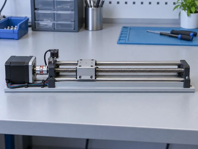
How Can Input Timing Become Position Variation?
A controller that reads a switch periodically may detect its transition after the carriage has already moved farther. The distance associated with a timing interval is approximately approach speed multiplied by that interval. This simple relationship explains why a final slow approach can reduce the position effect of an otherwise unchanged input path.
As an illustrative calculation, a carriage moving at 5 millimeters per second travels 0.025 millimeter in 5 milliseconds. This is the distance associated with that interval, not a prediction that every home cycle will have that error. Actual variation depends on sampling, filtering, sensor behavior, and whether the controller uses hardware capture.
Ask whether debounce and filtering act before or after the position is latched. A filtered status bit and a hardware-captured edge can describe different moments in the same movement. Test the implemented arrangement rather than inferring its performance from a scan-time specification alone.
Do not remove filtering merely to improve a timing calculation. An unstable input can generate a false reference that is much more disruptive than a small, repeatable delay. Sensor mounting and signal integrity should be checked alongside the control settings.
How Should the Measurement Setup Be Built?
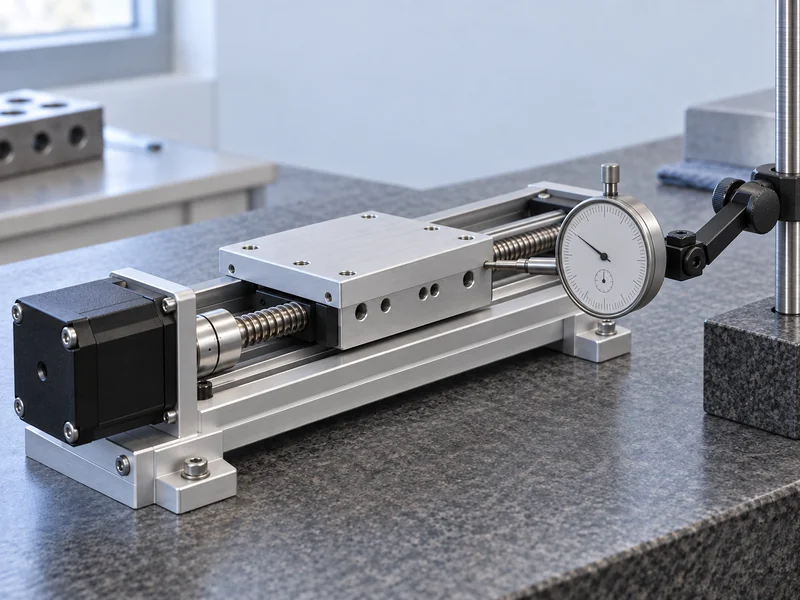
Use an independent measurement of the process datum after the complete homing sequence. A dial indicator may be adequate for a modest linear tolerance; tighter work may require a calibrated displacement sensor or another suitable reference. Its resolution and uncertainty should be small enough to distinguish the variation that the project needs to control.
Keep the instrument aligned with the measured motion and its support independent of loose guards or flexible covers. Confirm that contact force does not move the carriage. A changing bracket can create apparent homing variation even when the axis itself is consistent.
NIST’s measurement terminology guidance distinguishes repeatability under unchanged conditions from reproducibility when conditions change. Apply that distinction by first repeating one controlled setup, then deliberately changing the conditions listed in the qualification plan. Label the two sets of results separately.
| Test Group | Condition to Control |
| Baseline | Same starting region, temperature, load, and approach |
| Starting position | Several permitted initial positions, including an active sensor |
| Warm operation | Repeat after the representative production duty |
| Load variation | Repeat with the permitted process loads |
| Recovery | Repeat following the documented power-up sequence |
What Should Be Recorded During Each Trial?
Record the final measured position, initial location, sensor status, cycle outcome, and relevant temperature. Retain individual readings rather than only a mean. A narrow cluster containing one large excursion can be more significant to production than a slightly wider but predictable spread.
A development study might begin with a planned series of repeated cycles at each condition, but the number should reflect the risk and required evidence. A handful of successful cycles is useful for debugging, not strong evidence about rare failures. Agree on the sample count and acceptance method before collecting the qualification results.
Plot readings in execution order as well as summarizing their spread. A gradual shift suggests a changing condition such as warm-up or fixture movement; alternating values may point toward approach or mechanical play. These patterns help direct investigation without proving a particular cause by themselves.
Include failed and interrupted attempts in the record. Excluding every cycle that did not reach the final position can make an unreliable sequence appear exceptionally repeatable. Report completion reliability alongside the position statistics for completed cycles.
How Can Motor and Mechanical Errors Be Separated?
Compare the same axis at several stages of the sequence. Check whether the sensor transition is consistent, whether the captured reference is consistent, and whether the final offset move reaches the same measured location. A discrepancy introduced after capture deserves a different investigation from a wandering trigger point.
If the controller counts commands but the motor loses synchronization during withdrawal or the final move, the reported coordinate can look correct while the mechanism is elsewhere. The article on why stepper motors lose steps covers the broader causes. For this test, preserve the failing sequence and its load conditions before changing current or acceleration settings.
Check the sensor bracket, coupling security, screw support, and cable forces before assuming the motor requires replacement. A cable that bends differently near the travel limit can alter the disturbance applied to a small stage. Likewise, a reference mounted on a flexible enclosure may move relative to the tool datum as the machine warms.
For a new design, choose the stepper driver and controller together with the homing requirements. Verify their supported input logic, motion timing, and current settings in the proposed combination. The separate guide to choosing a stepper motor driver can help organize that discussion without replacing an axis-level test.
What Should the Supplier Receive Before Release?
Send a drawing identifying the measured datum, the complete homing state sequence, the operating-condition matrix, and the recorded results. Include the motor, driver, controller software, sensor, and mechanical revision used in the test. A successful sequence cannot be reproduced reliably if those identities are missing.
State the permitted spread, the acceptable reference offset, and the required behavior after a failed search. Assign responsibility for each setting and for any correction introduced after qualification. This gives purchasing and production a usable acceptance basis rather than an isolated demonstration that one prototype can find its switch.
Retain the approved record for later changes to the sensor, bracket, cable, driver, or motion software. Repeat the affected checks when a change can move the reference or alter its detection. The aim is a homing process whose meaning remains clear from the first sample through routine production.