
Field weakening may extend an inrunner BLDC motor’s usable speed, but only within verified electromagnetic, drive, thermal, and mechanical limits. Neither SPM nor IPM construction alone establishes safe high-speed operation.
Before choosing either topology, engineers need motor-specific magnetic evidence, minimum DC-link voltage, controller current capability, temperature-dependent demagnetization limits, and an accepted torque-speed validation plan.
Which Operating Requirements Should Be Defined Before Applying Field Weakening?
Field weakening should begin with the application’s operating requirements, not a preference for a particular rotor construction. The required speed, torque, voltage, and duty cycle determine whether field weakening offers a useful solution.
When reviewing an inrunner brushless DC motor, engineers should distinguish ordinary speed-control capability from an operating region that requires deliberate magnetic flux reduction.
How Does Field Weakening Extend Motor Speed?
As a permanent magnet motor accelerates, its back electromotive force (back-EMF) increases with speed. Eventually, the voltage required to maintain the commanded current approaches the inverter’s available output voltage.
Field-oriented control can introduce negative d-axis current, commonly written as Id, to oppose part of the permanent magnet flux linkage. This reduces voltage demand under suitable operating conditions.
The additional speed comes with restrictions. Negative Id consumes current capacity, while magnetic characteristics and voltage constraints determine how much torque-producing current remains available.
Engineers must also distinguish base speed, rated speed, and maximum permissible speed. Base speed depends on voltage and operating conditions; rated speed does not necessarily identify the field-weakening boundary.
What Application Requirements Must Be Defined First?
A field-weakening assessment needs a complete operating duty rather than one target speed. Speed alone cannot establish whether the motor can accelerate, sustain the load, or decelerate safely.
- Speed and torque: Record required operating points, including acceleration torque and load changes at higher speeds.
- Duty cycle: Separate continuous operation from short-duration demands and repeated speed transitions.
- Electrical supply: Identify nominal and minimum DC-link voltage, including expected supply sag.
- Cooling conditions: Define ambient temperature, installation orientation, airflow, and available heat-transfer paths.
- Stopping requirements: Identify regenerative operation, load-driven rotation, and expected fault responses.
These requirements establish the conditions for comparing motor candidates. A motor that reaches the desired speed without sufficient torque or thermal capacity is not a suitable selection.
How Do SPM and IPM Rotor Designs Affect Field-Weakening Capability?
The location of permanent magnets relative to the rotor core influences the electromagnetic characteristics of SPM and IPM motors. Those differences influence torque production and field-weakening control, but do not establish performance automatically.
Which Technical Characteristics Require Evaluation in SPM Inrunner Motors?
An SPM rotor carries permanent magnets on or near its outer surface. Its magnetic geometry generally produces relatively limited saliency compared with many IPM constructions.
Because the d-axis and q-axis inductances are often similar, reluctance torque is usually limited. Most torque comes from the interaction between permanent magnet flux and stator current.
SPM motors can still support field weakening when appropriate negative Id is available. The allowable current depends on magnet properties, temperature, and the complete electromagnetic design.
Surface magnet retention also requires attention. Adhesives, sleeves, rotor construction, and balancing must support the intended mechanical speed independently of electrical control capability.
Which Design Parameters Need Assessment in IPM Inrunner Motors?
An IPM motor places magnets within the rotor structure. Its magnetic paths can create different d-axis and q-axis inductances, allowing an additional reluctance-torque component.
This characteristic may help provide torque under certain voltage and current constraints. However, useful performance depends on actual flux linkage, saliency, saturation, and current-vector control.
Magnetic saturation can change inductance considerably as current increases. Cross-coupling also means that d-axis flux linkage may depend on q-axis current, and vice versa.
The embedded magnets introduce mechanical considerations involving rotor bridges, cavities, and local stresses. Their presence does not eliminate demagnetization or high-speed structural risks.
Why Is IPM Not Automatically Better Than SPM?
IPM construction may provide a useful field-weakening operating region, but greater saliency does not guarantee superior speed capability, efficiency, or continuous torque for every application.
An appropriately designed SPM motor may satisfy the required operating envelope with simpler magnetic behavior. Both designs require equivalent evidence before their actual suitability can be compared.
| Comparison Factor | SPM Inrunner Motor | IPM Inrunner Motor |
| Magnet arrangement | Magnets mounted on or near rotor surface | Magnets embedded within rotor |
| Magnetic saliency | Generally limited | Often more pronounced |
| Reluctance torque | Usually limited | Can contribute additional torque |
| Field-weakening capability | Depends on verified electrical and magnetic limits | Depends on verified saliency and electrical limits |
| Demagnetization assessment | Required | Required |
| Mechanical speed verification | Magnet retention and rotor integrity | Rotor bridges, cavities, and structural integrity |
| Selection basis | Validated operating envelope | Validated operating envelope |
The comparison must use the proposed motor designs, not representative topology assumptions. Published descriptions of SPM and IPM categories are insufficient evidence of a particular model’s saliency or field-weakening capability.
Which Electromagnetic Limits Must Be Verified Before Field Weakening?
Electromagnetic verification establishes whether the intended current vector can reduce voltage demand while maintaining torque without damaging the magnets. It requires actual motor parameters rather than generic SPM or IPM values.
Verify Back-EMF and Permanent Magnet Flux Linkage
Back-EMF measurements help establish the voltage associated with rotor speed. Engineers should request the measurement method, waveform, temperature, and constant definition before using these results.
Line-to-line and phase quantities must not be mixed. Peak and RMS conventions also matter when converting back-EMF data into the voltage quantities used by a controller model.
Permanent magnet flux linkage changes with temperature. This affects both back-EMF and torque production, so electrical predictions should cover the relevant operating temperatures.
The calculation should include winding resistance and inductive voltage terms under load. A no-load back-EMF constant alone cannot establish the loaded field-weakening boundary.
Check D-Axis and Q-Axis Inductance Under Saturation
The d-axis inductance, Ld, and q-axis inductance, Lq, influence the voltage required to regulate stator current. Their relationship also affects reluctance torque in salient motors.
Fixed inductance values provide a simplified model, but may become inaccurate under substantial magnetic saturation. This is particularly important when negative Id and high Iq occur together.
Cross-coupling changes the magnetic response of one axis as current changes on the other. Controllers using simplified parameters may therefore predict incorrect current angles or voltage requirements.
Where necessary, request current-dependent flux-linkage maps or suitably characterized inductance data. The supplier should identify measurement or calculation conditions and the model’s intended operating range.
Verify Negative D-Axis Current and Demagnetization Limits
Negative Id reduces effective d-axis flux linkage, but excessive opposing magnetic field can cause irreversible magnet demagnetization. The limit depends on magnetic design and magnet temperature.
Changes in magnet temperature can alter the permissible current limit, making a previously acceptable current level unsuitable. Engineers need the allowable negative-current boundary for the relevant magnet conditions.
The assessment must also consider current overshoot, rotor-position error, and fault transients. A steady-state negative Id limit cannot automatically be used as a safe transient limit.
For each proposed motor, distinguish permissible operating current from the current that could cause irreversible damage. Do not infer either value from topology alone.
Check the Current Circle and Torque-Producing Current
For a conventional d/q model using consistent current definitions, the current magnitude constraint can be written as Id² + Iq² ≤ Imax².
Here, Imax represents the applicable current-vector limit. It must be consistent with the controller’s phase-current convention and the motor’s continuous or transient current allowance.
As negative Id increases in magnitude, less current capacity may remain for Iq. This can reduce available torque even while extending the voltage-limited speed range.
IPM torque may also include a reluctance component, so remaining Iq alone cannot determine the result. Evaluate the magnetic torque model at the actual current-vector operating point.
Can the Inverter and Control System Support Field Weakening?
A motor with suitable magnetic characteristics still needs an inverter capable of generating and regulating the required current vector. The controller’s electrical and software limitations form a separate verification boundary.
Verify Minimum DC-Link Voltage and Modulation Limits
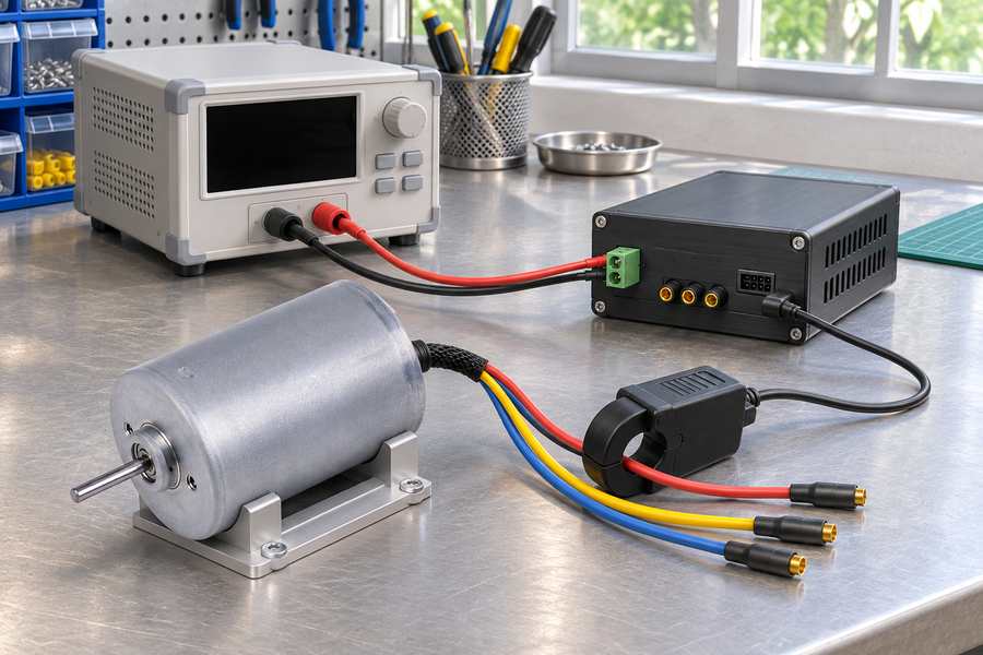
Field-weakening calculations should use the lowest DC-link voltage expected during the required operating duty. Nominal supply voltage may overstate the inverter voltage available under load.
Battery discharge, cable losses, source impedance, and load transients can reduce voltage. Their relevance depends on the actual power-supply arrangement and installation.
The inverter’s modulation method determines its usable fundamental output voltage. Dead time, semiconductor voltage drops, and current-regulation reserve further influence the practical operating boundary.
Engineers should verify that commanded d/q voltage remains achievable during acceleration and load changes. Sustained voltage saturation may prevent the controller from tracking the required current.
Confirm Six-Step or FOC Control Compatibility
Conventional six-step commutation energizes motor phases according to discrete rotor-position sectors. Commutation advance may alter high-speed operation, but does not provide independently regulated d-axis and q-axis currents.
Field-oriented control (FOC) directly regulates these current components using rotor-position information and coordinate transformations. This provides a suitable framework for controlled negative Id operation.
However, FOC availability does not prove that field weakening is implemented correctly. Current sensing, position accuracy, voltage limiting, and controller firmware must support the intended operation.
Depending on the motor characteristics and operating conditions, the controller may benefit from maximum torque per ampere (MTPA) or maximum torque per voltage (MTPV) control. Their usefulness depends on motor parameters, controller implementation, and the required operating region.
Advanced six-step strategies should be assessed on their own demonstrated capabilities. They should not be treated as equivalent to closed-loop d/q field-weakening control without verification.
Evaluate Rotor Position Observability Under Sensorless Control
Instead of relying on a physical position sensor, sensorless algorithms infer the rotor’s angular position using measured electrical signals and a suitable motor model. Its reliability depends on the estimation method, motor characteristics, operating speed, and available measurement information.
Back-EMF-based estimation generally becomes difficult near standstill because the available signal decreases. Saliency-based estimation has different requirements and cannot be assumed suitable for every motor.
During high-speed field weakening, voltage saturation, parameter errors, and distorted current responses can degrade position estimation. Incorrect position estimates also produce incorrect d/q current components.
Validation should include acceleration, field-weakening entry, steady operation, and deceleration. Sudden load changes are especially useful for identifying estimator instability or inadequate current regulation.
If sensorless performance cannot meet the operating requirements, evaluate an appropriate rotor-position sensor and its integration rather than relying on unspecified controller tuning.
Verify Electrical Fault Handling and Controller Protection
Protection requirements extend beyond normal current regulation. A controller must respond appropriately when its estimated rotor position, current feedback, or available DC-link voltage becomes unreliable.
- Current-regulation faults: Verify detection and response when commanded current cannot be maintained.
- Position errors: Evaluate incorrect current-vector orientation and possible demagnetizing transients.
- Regenerative overvoltage: Check DC-link energy handling during deceleration and load-driven rotation.
- Control interruption: Determine the mechanical consequences of losing inverter torque at high speed.
- Overspeed protection: Confirm detection methods and the required protective response.
Electrical shutdown does not automatically bring a rotating load to rest. The fault strategy must account for stored kinetic energy and the mechanical system’s stopping requirements.
What Torque-Speed and Thermal Limits Must Be Verified?
Electromagnetic feasibility establishes possible operating points, but thermal limits determine how long they can be maintained. Engineers need a torque-speed-thermal envelope tied to actual cooling and duty conditions.
Confirm the Available Torque-Speed Operating Envelope
The required load torque should be compared against the available motor torque throughout the proposed speed range. A single maximum-speed value cannot establish application suitability.
Continuous and short-duration torque must be assessed separately. Field weakening may permit higher speed while leaving insufficient current or voltage margin for acceleration or disturbance rejection.
Do not assume that the motor provides constant power throughout the field-weakening region. That behavior depends on its actual magnetic characteristics, current limits, and voltage constraints.
Request an operating map identifying base-speed conditions, field-weakening boundaries, available torque, and the assumptions used to calculate or verify each operating point.
Evaluate Motor and Inverter Losses During Field Weakening
Negative d-axis current contributes to winding copper losses even when it does not directly produce the desired shaft torque. Additional current may therefore increase heating disproportionately.
Higher rotational speed can increase iron losses and applicable rotor losses. Their magnitude depends on magnetic material, flux distribution, electrical frequency, and the control strategy.
Inverter conduction and switching losses also affect system thermal performance. These losses should be evaluated at the intended current, modulation state, and switching conditions.
A motor that meets an electromagnetic torque target may still fail thermal acceptance during sustained operation. Loss estimates need confirmation against appropriate thermal evidence.
Check Winding and Magnet Temperature Limits
Winding temperature affects resistance and copper losses. Magnet temperature changes magnetic flux and demagnetization resistance, potentially altering both torque capability and allowable negative Id.
Cold and hot operating conditions can produce different voltage and magnetic limitations. Neither condition should automatically be treated as the sole worst case.
Cooling assumptions must reflect the installation, including housing contact, airflow, surrounding components, and operating duration. A free-air result may not represent an enclosed assembly.
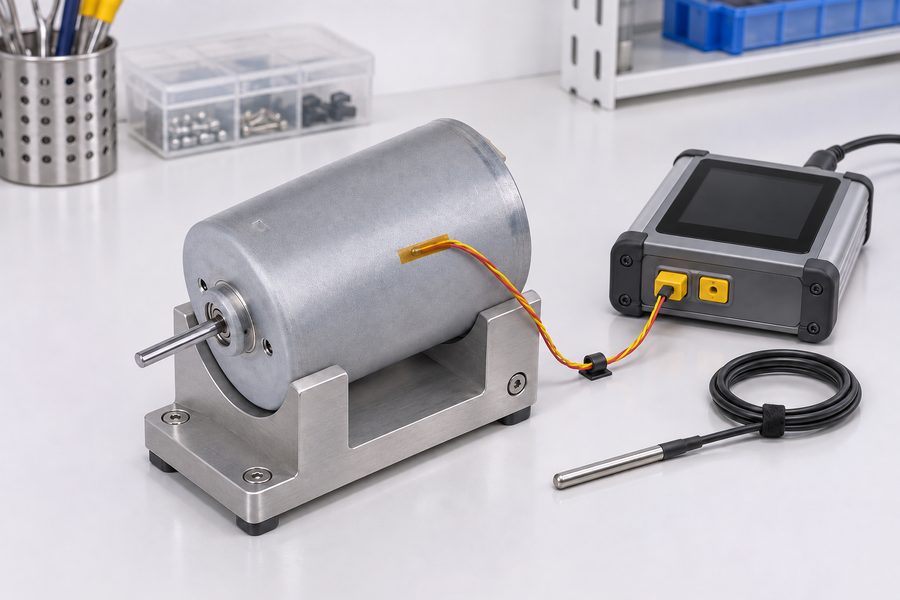
Acceptance evidence should identify winding temperatures, estimated or measured magnet temperatures, cooling conditions, and the duration of each verified operating point.
What Mechanical Speed Limits Must Be Checked?
Electrical field weakening cannot increase the rotor’s permissible mechanical speed. Mechanical verification must independently establish that the entire rotating assembly can withstand the required operating conditions.
Verify Rotor Strength and Magnet Retention
Centrifugal loading increases with rotational speed. Rotor materials, magnet retention arrangements, and manufacturing tolerances therefore influence the maximum permissible speed of the completed rotor assembly.
SPM constructions require attention to surface magnet retention and any retaining sleeve. IPM designs require assessment of embedded magnet support, rotor bridges, and local structural stresses.
Neither construction should be assigned a mechanical advantage without model-specific analysis or validation. The verified limit must apply to the actual rotor geometry and manufacturing configuration.
Check Bearings, Shaft Design, and Rotor Dynamics
Bearing suitability depends on operating speed, lubrication, temperature, and applied loads. High-speed electrical capability does not confirm that the bearings can sustain the intended duty.
Shaft configuration also affects mechanical behavior. Changes in shaft length, diameter, coupling arrangement, or external load can influence bending, vibration, and rotor dynamic response.
Balancing quality and critical-speed behavior require attention where relevant. Engineers should consider both steady operating speed and the speed range crossed during acceleration or deceleration.
Confirm Overspeed and Stopping Requirements
The controller’s speed limit should be coordinated with the rotor’s verified mechanical limit. Position-estimation errors and delayed fault responses must be considered when establishing protective behavior.
High-inertia or externally driven loads may continue rotating after electrical torque is removed. The stopping method must therefore be compatible with the application and stored mechanical energy.
Where braking is regenerative, available DC-link energy absorption becomes relevant. Mechanical stopping requirements and electrical overvoltage protection must be evaluated together, not as unrelated functions.
What Evidence and Tests Are Required Before Approving Field Weakening?
Approval requires traceable evidence for the proposed motor and inverter combination. Generic motor specifications, topology descriptions, and controller feature lists do not establish a verified field-weakening operating envelope.
Request Motor-Specific Technical Data
Begin by identifying the exact motor construction, winding configuration, rotor revision, and proposed controller. Magnetic and mechanical data must correspond to that configuration.
Request evidence covering electromagnetic parameters, allowable current, temperature-dependent demagnetization limits, rotor speed capability, and the required torque-speed operating region.
| Verification Area | Required Evidence | Main Concern |
| Rotor topology | Model-specific SPM or IPM construction confirmation | Incorrect topology assumptions |
| Back-EMF | Measured or validated characteristics with conventions | Incorrect voltage prediction |
| Magnetic parameters | Flux linkage and current-dependent d/q characteristics | Inaccurate control model |
| Negative Id | Temperature-dependent permissible limits | Irreversible demagnetization |
| DC-link and modulation | Minimum operating voltage and usable inverter output | Insufficient voltage margin |
| Current limits | Continuous and transient motor-controller limits | Overcurrent or reduced torque |
| Torque-speed capability | Validated operating map | Insufficient high-speed torque |
| Thermal behavior | Temperature data under defined cooling and duty conditions | Overheating |
| Mechanical speed | Rotor and bearing speed verification | Mechanical failure |
| Control and protection | Controller capability and fault-response evidence | Loss of regulation or overspeed |
Validate the Motor and Inverter Together
Motor calculations should be checked against the intended inverter and controller settings. A suitable motor cannot compensate for inadequate voltage utilization, unstable current regulation, or unreliable rotor-position estimation.
Testing should cover representative high-speed load points and the transitions entering and leaving field weakening. Record actual DC-link voltage rather than assuming it remains constant.
- Voltage verification: Confirm adequate current regulation at minimum expected DC-link voltage.
- Current tracking: Compare commanded and measured d/q currents during steady operation and transients.
- Torque capability: Establish that required torque remains available across the proposed speed range.
- Thermal operation: Check relevant winding, rotor, and inverter temperatures under representative duty.
- Control stability: Evaluate field-weakening transitions, sensorless estimation, and load disturbances.
- Fault responses: Verify applicable current, voltage, position, and overspeed protection behavior.
Test records should identify equipment configuration, measurement conditions, controller settings, and acceptance criteria. Results from a different winding or controller version should not automatically be transferred.
Define Acceptance Criteria Before Final Selection
Acceptance criteria should identify required torque at specified speeds, minimum DC-link voltage, permissible current, thermal conditions, and the maximum allowable mechanical speed.
Each criterion needs supporting analysis or validation. Unverified extrapolation beyond measured conditions should remain clearly identified rather than being presented as confirmed operating capability.
How Should Engineers Choose Between SPM and IPM Inrunner Motors?
Selection should follow verified operating requirements and supplier evidence. SPM and IPM are construction categories, not substitutes for electromagnetic characterization or system-level validation.
When May an SPM Inrunner Motor Be Suitable?
An SPM design may be appropriate when its verified voltage and current limits permit the required speed and torque without exceeding allowable negative Id.
Magnet retention, rotor speed, temperature, and controller behavior must also satisfy the duty. Relatively limited saliency does not automatically prevent useful field-weakening operation.
When May an IPM Inrunner Motor Be Suitable?
An IPM design may be appropriate when its verified saliency and magnetic characteristics support the required current-vector trajectory and deliver useful torque within available voltage.
Its reluctance-torque contribution must be evaluated alongside saturation, cross-coupling, magnet limits, and rotor stresses. IPM construction alone cannot establish a wider usable speed range.
When Should Field Weakening Be Avoided?
Field weakening should not be approved when essential parameters remain unknown or the operating duty exceeds verified electrical, magnetic, thermal, or mechanical limits.
Alternative winding configurations, supply voltage, motor geometry, or a different motor selection may provide a more suitable operating envelope without relying on unsupported negative-current operation.
What Should Buyers Confirm With Gian Transmission?
Gian Transmission offers customization involving inrunner motor dimensions, shaft configurations, windings, and voltage requirements. These options support design discussions but do not independently establish field-weakening suitability.
The broader brushless DC motor customization options can help buyers define electrical and mechanical requirements. Actual SPM/IPM construction and magnetic characteristics still require confirmation for the proposed model.
Before releasing a specification or purchase approval, buyers should obtain the following records for the agreed motor-controller configuration.
- Configuration record: Confirm motor model, rotor topology, winding revision, shaft arrangement, and controller identification.
- Electromagnetic record: Obtain available back-EMF, flux-linkage, inductance, saturation, and negative Id evidence.
- Electrical acceptance: Document minimum DC-link voltage, current limits, modulation strategy, and verified operating points.
- Thermal acceptance: Identify the permitted duty cycle, cooling conditions, and winding and magnet temperature boundaries.
- Mechanical acceptance: Confirm permissible rotor speed, bearing suitability, and relevant structural verification.
- Control acceptance: Document field-weakening settings, rotor-position feedback, current regulation, and applicable fault responses.
- Validation record: Retain test conditions, measured results, outstanding limitations, and responsible approval personnel.
The final acceptance document should state exactly which speed-torque operating points are approved, under which voltage and temperature conditions, and which operating regions remain unverified.
Any later change to winding configuration, rotor construction, controller firmware, or cooling arrangement should trigger a review of affected evidence before the revised configuration is approved.