
A robot joint’s torque rating does not establish whether its output can support the arm attached to it. Bearings and housing must also carry radial force, axial force, and overturning moment while maintaining acceptable stiffness and life. Specify those loads separately and trace how they reach the fixed structure before selecting the motor or gearbox.
This matters when a compact geared motor is asked to act as both drive and structural joint. Its gears may transmit enough torque, yet its output shaft or bearings may be unsuitable for a long cantilevered link. The result can be deflection, friction, wear, or damage despite operating below the stated torque limit.
Which Loads Are Missing From a Torque-Only Calculation?
Driving torque acts about the intended rotation axis. Radial and axial forces act across or along that axis, while an offset force can create a moment that tries to tilt the output. These loads can occur simultaneously and change as the robot moves.
Draw a free-body diagram of the tool and the structures beyond the joint. Include gravity, acceleration, contact forces, belt tension where relevant, and any cable forces large enough to matter. Then resolve the resulting forces and moments at the output interface.
MIT’s mechanical component design notes discuss bearing arrangements and the moment loads encountered in robot arms. The practical lesson is to select the support arrangement for the actual load path rather than assuming any rotary bearing provides the same support.
When evaluating a planetary gear motor, request its external load limits and the associated conditions. Ask where the load is applied, whether combined loads are covered, and how speed and required life affect the selection.
How Does Tool Offset Change Bearing Demand?
Moving a force farther from the support increases its moment about that support. With force acting perpendicular to the lever arm, calculate the moment as M = F × L. This can raise the demand on a bearing arrangement without changing the useful driving torque in the same way.
As an illustrative example, a 40 N force acting at an offset of 0.12 m creates a 4.8 N·m moment about the support reference. Doubling the offset doubles that moment even though the force stays the same. These example values describe statics, not the capacity of a particular joint.
A longer tool or adapter can therefore change the bearing requirement substantially. Record both the force and its location, and consider the worst permitted tool arrangement. A payload mass without its center of mass is an incomplete input for joint support design.
Do not confuse this overturning moment with torque about the joint’s driven axis. They may use the same units while loading different aspects of the assembly. The supplier needs their directions and reference point to evaluate the combination correctly.
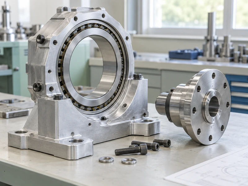
Why Does Bearing Arrangement Matter as Much as Bearing Size?
The arrangement determines how loads are shared and how the shaft resists tilting. Two appropriately spaced supports can react a moment differently from a single short support. Specialized bearing arrangements may carry combined loads, but their performance depends on mounting and the manufacturer’s design rules.
Consider the surrounding structure. A bearing with adequate catalog capacity can still perform poorly if its housing distorts or its shaft shoulder does not locate it correctly. Fits, retention, alignment, and assembly condition all contribute to the result.
The University of Rochester’s robot-joint construction notes distinguish radial and axial loading and explain why bearing selection must match the load direction. Treat the general examples as educational guidance, then use current bearing data for the final design.
For a compact harmonic drive motor assembly, establish whether the output support is integrated and which loads it is designed to carry. The transmission architecture alone does not determine the capacity of every product using it.
When Should External Bearings Be Added?
Add an external support arrangement when the selected motor or gearbox cannot carry the required external loads, or when the required stiffness and load path justify a separate support. The support should be designed with the drive connection rather than attached as an afterthought. Extra bearings can introduce alignment problems if the system becomes unintentionally overconstrained.
One approach is to let a dedicated joint bearing structure carry the arm while the motor and reducer transmit torque through a suitable connection. This can separate structural loading from the reducer output. The comparison must also allow for the additional bearing hardware, occupied volume, and installation work.
Review how axial location and thermal expansion are managed. Multiple rigidly locating elements can fight one another as dimensions change. The bearing and coupling manufacturers’ guidance should inform the final arrangement.
GIAN’s gear motor sizing guide is useful for the drive requirement. Add a separate support calculation so that meeting the torque-speed demand is not mistaken for qualifying the entire joint.
How Should Stiffness Be Evaluated?
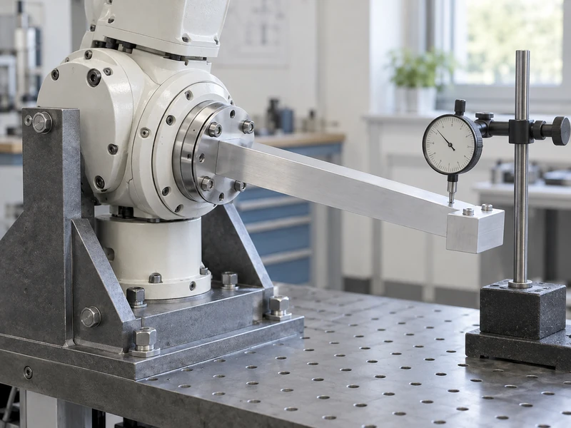
Measure displacement at a reference relevant to the task under representative force and moment. The output may tilt as well as rotate, and the tool can amplify small angular movement. A bearing arrangement that survives the load may still be too flexible for the positioning requirement.
Distinguish stiffness from backlash and from strength. Clearance-related motion, elastic deflection, and permanent deformation are different behaviors. The acceptance method should identify which one is being measured instead of reducing them to a single claim that the joint is tight.
| Requirement | Question for the Joint Supplier |
| External force capacity | Which radial and axial loads are permitted together? |
| Overturning moment | What reference point and load offset apply? |
| Stiffness | What displacement occurs under the specified load? |
| Life | Which load spectrum, speed, and operating conditions were used? |
| Mounting | Which fits, flatness, fasteners, and assembly settings are required? |
GIAN’s explanation of planetary gearbox backlash provides related context on support and assembly influences. If the tool moves under load, inspect the entire mounting chain before assigning the error to the gear teeth.
What Changes During Repeated Robot Motion?
The load magnitude and direction can vary throughout the trajectory. Acceleration, deceleration, contact events, and different tool orientations create a load spectrum rather than one constant value. Bearing life assessment and joint qualification should reflect that spectrum.
Some robot joints also make small oscillating movements instead of continuous rotations. Lubrication and contact behavior under those movements may differ from a simple continuously rotating catalog example. Describe the actual travel and dwell pattern when requesting bearing guidance.
Check the installed assembly after warmup and after a defined cycle test. Increased running resistance, changed position behavior, or loosened retention can indicate a developing issue. A quieter sound or a lower motor current alone is not a complete bearing-condition assessment.
Use controlled testing with the intended mounting structure and load offsets. An unloaded reducer sitting on a bench does not reproduce the bending moment of a long arm. Keep sensor locations and measurement references consistent so that changes are attributable to the assembly.
How Can a Mounting Problem Be Distinguished From a Bearing Problem?
Measure movement at more than one point along the load path. Compare the output flange, housing, mounting plate, and fixed reference under the same applied load. If much of the displacement occurs between the housing and base, a bearing change may not address the dominant error.
Inspect mounting-face contact and fastener condition before increasing preload or selecting a larger bearing. An uneven mounting surface can distort a compact housing, while a flexible bracket can make a stiff joint appear compliant. Follow the assembly requirements for the actual components instead of tightening until movement seems to disappear.
Why Should the Installed Condition Be Recorded?
Because the same reducer can behave differently in different fixtures. Record the mounting geometry, fastener specification, tightening procedure, load offset, and measurement reference. Those details make it possible to distinguish a component change from a change in how the component was supported.
For an illustrative diagnosis, suppose a joint passes a rigid bench test but deflects excessively after installation on a thin robot link. Measure the link and mounting interface before rejecting the bearing selection. Reinforcing the local support may be the relevant correction.
Repeat the application test after the correction, including representative movement and warmup. A better static reading alone does not establish that the revised assembly has acceptable friction, thermal behavior, and dynamic response throughout its duty cycle.
What Information Makes Selection More Reliable?
Provide a drawing with the output axis, load application points, mounting faces, and tool envelope. Add the forces and moments over representative motions, required positioning performance, operating environment, and service expectations. Where the loads are still estimates, identify the uncertainty explicitly.
GIAN’s guide to planetary gear motors for robotics can help organize the wider selection. The bearing review then turns a general motor choice into a joint-specific engineering discussion.
The final specification should explain both how the joint moves the arm and how it supports the arm. A suitable torque rating answers the first question only in part. Verified bearing loads, stiffness, mounting, and duty-cycle performance complete the information needed for a dependable robot joint.