
Bell runout describes indicated variation on a rotating bell surface; shaft runout describes variation on a rotating journal. Comparing them requires a defined axis, not an assumption that their readings should match.
Use stable stationary mounting, unpowered manual rotation, correct indicator directions, and repeated angular mapping. Separate setup error and bearing play before applying model-specific limits from approved drawings.
How Do Bell and Shaft Runout Measurements Differ?
An outrunner BLDC motor has a rotating outer structure, making its geometry different from that of a conventional motor with a stationary outer housing.
Accurate inspection begins by identifying which surface is measured, which component rotates, and what reference establishes the measurement axis. These distinctions prevent misleading comparisons.
Radial Bell OD Runout
Radial bell runout is the total indicator variation measured on the rotating bell’s outer cylindrical surface. The indicator measures displacement in a direction approximately perpendicular to the rotation axis.
Measured variation may reflect eccentricity, out-of-roundness, localized surface imperfections, or movement within the supporting assembly. A single reading cannot distinguish these contributions.
The outer bell diameter may also serve primarily as a protective or cosmetic surface. Unless drawings identify it as an inspection feature, its runout may not establish functional acceptance.
Axial Bell Face Runout
Axial bell face runout measures indicated displacement along the motor’s rotation axis while a selected face surface rotates beneath the indicator contact.
Face tilt, surface waviness, and axial bearing movement can influence the measurement. The contact radius matters because angular face deviation produces different displacement at different radial positions.
Radial bell runout and axial face runout therefore describe separate geometric characteristics. Motor alignment assessments must consider each measurement independently.
Rotating Shaft Journal Runout
Shaft journal runout measures radial indicator variation on a specified rotating cylindrical shaft surface. The measurement is meaningful only when the inspected journal rotates relative to the stationary indicator.
Even when the shaft and bell rotate together, their readings may differ because of mounting interfaces, geometric errors, bearing motion, and individual surface conditions.
Some outrunner motors instead use stationary shafts. In these arrangements, rotating the bell does not rotate the shaft journal, so a different shaft inspection method is necessary.
| Measurement Type | Measured Surface | Indicator Direction | Main Purpose |
| Radial Bell OD Runout | Rotating bell outer diameter | Radial | Evaluate indicated cylindrical surface variation |
| Axial Bell Face Runout | Rotating bell face | Axial | Evaluate indicated face variation at a specified radius |
| Rotating Shaft Journal Runout | Rotating shaft journal | Radial | Evaluate journal variation relative to the inspection reference |
| Stationary Shaft Geometry | Fixed shaft features | Depends on geometric characteristic | Evaluate straightness, form, or alignment using an appropriate separate setup |
How to Set Up an Outrunner BLDC Motor for Accurate Runout Inspection
Inspection setup determines whether indicator movement represents a motor characteristic or a measurement artifact. An unstable reference can produce repeatable-looking readings that do not describe the intended feature.
Identify the Rotating Components and Approved Datums
Examine the assembly drawing before mounting the motor. Identify the stationary support, rotating bell, bearing arrangement, and shaft configuration associated with the inspected assembly.
Shaft sizes and mounting designs differ across outrunner brushless DC motor configurations. The approved drawing must establish the actual configuration and relevant inspection requirements.
A datum is a defined geometric reference, not simply the nearest accessible surface. A nominal mounting centerline may differ from the actual operating rotation axis.
If a drawing specifies runout relative to particular mounting or bearing-related features, the fixture must reproduce that reference relationship sufficiently for the intended inspection.
Secure the Stationary Motor Structure
Support the motor through its intended stationary structural interface. The fixture should prevent housing displacement while allowing unrestricted manual rotation of the bell.
Mounting pressure must not distort the assembly or alter bearing alignment. Avoid clamping thin covers or nonstructural surfaces merely because they are convenient.
Check the fixture for looseness before measuring. Confirm that indicator supports remain stationary when the bell is gently rotated without significant radial or axial force.
Keep the motor electrically unpowered during inspection, and prevent unintended energization. Remove any external interference that could restrict rotation or disturb the indicator.
Select and Position the Dial Indicator
Select an indicator with adequate resolution, travel, and suitable contact geometry for the expected measurement. Instrument suitability depends on the drawing requirement and inspection uncertainty.
For radial measurement, align the indicator’s sensitive direction approximately normal to the cylindrical surface. For axial measurement, align it parallel to the rotation axis.
Incorrect contact alignment can introduce directional measurement errors. Excessive preload can also influence a lightly supported rotor through bearing clearance or structural deflection.
Before collecting results, establish the following inspection conditions:
- Contact surface: Choose a suitable continuous measurement band without openings, labels, or discontinuities that disrupt indicator travel.
- Contact force: Apply sufficient preload for continuous contact without unnecessarily displacing the rotating assembly.
- Indicator travel: Verify that the probe remains within its usable range throughout rotation.
- Angular reference: Establish a repeatable bell position for comparing measurements across revolutions.
How to Measure Radial and Axial Bell Runout
Bell inspection should evaluate radial and axial variation independently. Both measurements use manual rotation, but their contact directions, geometric interpretations, and acceptance requirements differ.
Measure Radial Runout on the Bell Outer Diameter
Choose the specified cylindrical inspection surface and position the indicator radially against it. Avoid contact bands containing significant texture, seams, or localized surface features.
Zero the indicator at a convenient starting position, then rotate the bell slowly through one complete revolution. Maintain consistent handling without pushing the rotor sideways.
Observe the maximum and minimum readings. Total indicated reading, commonly abbreviated TIR, is calculated by subtracting the minimum indicated value from the maximum.
For an illustrative calculation, suppose the maximum reading is +0.04 mm and the minimum is -0.03 mm. The resulting TIR is 0.07 mm.
These values demonstrate the calculation only. They are not motor specifications, inspection results, or acceptable limits for any Gian Transmission product.
Repeat the revolution and compare the reading pattern. A different result after changing contact pressure or rotation technique suggests that measurement conditions require further attention.
Measure Axial Runout on the Bell Face
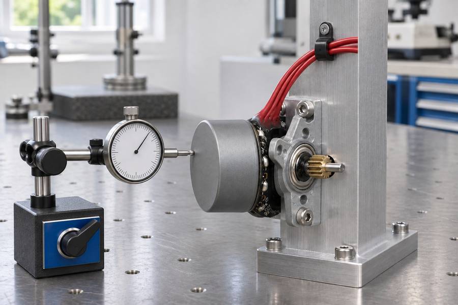
Move the indicator to a suitable rotating face surface and orient its measuring direction parallel to the motor’s rotation axis.
Record the radial distance between the rotation axis and contact point. This information is essential when comparing face measurements taken at different locations.
Rotate the bell manually while observing maximum and minimum readings. Avoid pulling or pressing the bell axially during rotation because bearing movement can affect the result.
Repeat the measurement at the same contact radius to check consistency. If required, inspect additional radii while preserving the same reference and setup conditions.
A difference between inner and outer face readings may indicate angular face variation, but surface form and assembly movement must be considered before assigning a cause.
Map Runout Readings Across Repeated Rotations
A maximum-minus-minimum result provides the overall indicated variation but does not show how that variation is distributed around the rotating component.
Mark a repeatable angular origin on a suitable surface. Record indicator readings at consistent angular positions over at least one complete revolution.
Repeat the sequence using the same contact position and fixture arrangement. Compare the angular locations of high and low readings rather than considering TIR alone.
- Consistent angular pattern: Suggests a reproducible relationship between rotation and measured surface variation.
- Changing peak location: May indicate inconsistent contact, assembly movement, or an unstable measurement reference.
- Localized reading change: Can indicate a surface irregularity that requires separate geometric inspection.
- Different axial positions: May reveal changes in the indicated surface geometry along the bell.
Angular mapping improves troubleshooting, but it does not independently identify eccentricity, shaft bending, or bearing defects. Those conclusions require additional supporting measurements.
How to Inspect Shaft Journal Runout Without Confusing It with Bell Runout
Shaft inspection requires a separate decision about motor construction. The important question is whether the shaft journal actually rotates during normal operation.
Measure Shaft Runout on Rotating-Shaft Outrunners
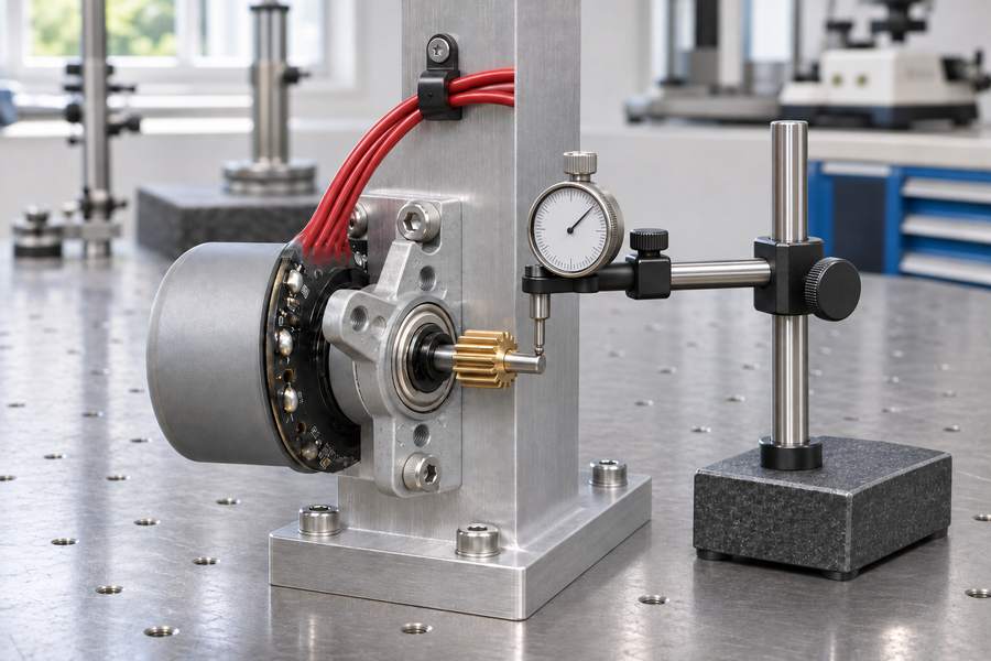
For a rotating-shaft configuration, locate the journal specified for inspection. Avoid threads, damaged surfaces, keyways, and transitions unless the drawing explicitly requires their evaluation.
Support the stationary motor structure and position the indicator radially against the rotating journal. Maintain a stable contact position throughout manual rotation.
Record maximum and minimum readings over a complete revolution. Calculate the journal TIR separately from the bell measurement and repeat the inspection to establish consistency.
If multiple shaft locations are specified, document each location individually. Measurements closer to or farther from the bearings can respond differently to shaft geometry and assembly motion.
Do not interpret a large journal reading as proof of a bent shaft. Incorrect reference alignment, bearing movement, and journal form errors can produce similar observations.
Evaluate Shaft Geometry on Stationary-Shaft Outrunners
In stationary-shaft designs, the shaft remains fixed while the surrounding bell rotates. A stationary indicator contacting that shaft will not generate operating shaft journal runout.
Shaft straightness, cylindricity, or alignment may still require inspection, but the method must match the characteristic defined on the approved drawing.
For example, a shaft may require inspection in a separate fixture using specified datum features. That setup evaluates the relevant shaft geometry rather than bell-driven journal motion.
Rotating the complete motor within an external fixture also creates a different reference condition. Such a measurement must not automatically be called operating shaft runout.
Compare Bell and Shaft Results Without Assuming a Common Cause
When both shaft and bell rotate together, their readings can be compared at defined angular positions, provided the setup preserves a common angular reference.
Similar reading patterns may suggest a shared geometric or assembly influence. Different patterns may indicate feature-specific variation, but neither observation proves a particular defect.
Compare not only TIR magnitude but also contact location, angular phase, measurement direction, and repeatability. Different surfaces can produce different readings under the same rotation.
For stationary-shaft designs, compare the separately established shaft geometry with the bell measurements only through their documented datum relationships. Do not equate unlike measurements.
How to Separate Bell, Shaft, and Measurement Setup Errors
Unexpected runout readings should be investigated systematically. Rechecking the motor without examining the measurement setup can repeatedly reproduce an incorrect interpretation.
Check Fixture Stability and Datum Alignment
Begin by checking fixture fasteners, mounting contact surfaces, and indicator support stability. Movement anywhere in the reference structure can appear as motor runout.
Inspect whether the selected reference represents the intended drawing datum. A misaligned fixture can change the relationship between the indicator and rotating surface.
Repeat the inspection after correcting visible setup problems. If remounting produces materially different results, evaluate fixture repeatability before attributing variation to the motor.
Identify Bearing Clearance and Mechanical Play
Bearing clearance can permit small radial or axial displacements under applied force. These movements are distinct from repeatable geometric variation during unloaded rotation.
Manual handling and indicator contact force may shift the assembly within its available clearance. Excessive or inconsistent force can therefore change apparent runout.
Check whether readings vary with handling direction or controlled changes in contact conditions. Avoid applying force that could damage bearings or deform motor components.
Bearing play requires separate evaluation when relevant. A runout measurement alone cannot establish bearing condition, internal clearance compliance, or expected service life.
Distinguish Surface Form Errors from Eccentricity
A perfectly circular cylinder mounted with an offset center produces a different geometric condition from an out-of-round cylinder centered on its intended axis.
Both conditions can create indicator variation. Local dents, machining marks, or uneven finishing can introduce additional peaks that complicate the resulting measurement pattern.
A cosmetic bell diameter may be particularly unsuitable for judging precision alignment if its geometry is not controlled as a functional feature.
When readings cannot distinguish form error from offset, use an appropriate geometric inspection method and reference scheme rather than assigning eccentricity directly from TIR.
Use Measurement Patterns to Guide Further Diagnosis
Comparing repeatable patterns across measurement locations helps identify which components or measurement conditions deserve investigation. However, pattern similarity alone cannot establish mechanical causation.
| Observed Measurement Pattern | Possible Contributing Error | Additional Verification | Inspection Action |
| Bell OD variation with low rotating shaft TIR | Bell geometry or mounting relationship | Check bell surface form and approved datums | Inspect the bell feature independently |
| Shaft journal variation with a different bell pattern | Journal geometry or assembly influence | Repeat journal measurements at specified locations | Investigate shaft and bearing-related contributions |
| Similar bell and rotating shaft patterns | Shared rotation-related variation | Compare angular phase and reference stability | Perform independent feature checks |
| Readings change after remounting | Fixture or datum repeatability | Check mounting contact and alignment | Correct setup before evaluating acceptance |
| Readings change with contact pressure | Bearing play or structural deflection | Control probe and handling forces | Investigate assembly movement separately |
| Axial readings vary with manual force | Axial play or fixture movement | Repeat without unintended axial loading | Separate face geometry from axial displacement |
Use these observations to determine the next inspection step, not to assign an automatic root cause. Confirmation requires measurements that isolate the suspected source.
How to Interpret TIR, Eccentricity, and Dynamic Imbalance
What Does Total Indicated Reading Actually Represent?
Calculate TIR by subtracting the lowest recorded indicator value from the highest within one measurement cycle. It describes observed variation under those specific conditions.
The value depends on the measured surface, indicator orientation, reference arrangement, and assembly behavior. Identical TIR values can arise from different geometric conditions.
Consequently, reporting TIR without identifying the measured feature and setup provides insufficient information for meaningful engineering comparison or drawing-based acceptance.
Why TIR Is Not Automatically Twice the Eccentricity
Consider a perfectly circular cylindrical surface whose center is offset from a stable rotation axis. Under ideal radial measurement conditions, TIR equals twice that offset.
For an illustrative calculation, an ideal circular surface with a 0.02 mm center offset would produce approximately 0.04 mm radial TIR.
This relationship applies to the simplified pure-eccentricity case. Out-of-roundness, surface imperfections, bearing movement, and reference errors can change the observed variation.
Therefore, dividing every measured TIR value by two does not reliably establish actual eccentricity. Additional geometric characterization may be required to determine the center offset.
Why Geometric Runout Does Not Establish Dynamic Balance
Geometric runout describes the indicated movement of a measured surface relative to a reference. Dynamic imbalance concerns rotating mass distribution and its resulting effects during operation.
A rotor can exhibit relatively low geometric runout while having uneven mass distribution. Conversely, detectable surface runout does not by itself quantify rotor imbalance.
Balance assessment may require separate evaluation of mass distribution, operating conditions, and vibration behavior. Manual dial indicator inspection cannot replace those assessments.
Motor acceptance should therefore distinguish geometric requirements from balance or vibration requirements whenever the application depends on both.
How to Record Runout Results and Apply Drawing-Based Acceptance Criteria
Document Measurement Conditions and Results
An inspection record should allow another technician to reproduce the measurement without guessing which component, datum, or indicator location was used.
Record the following information for each measured feature:
- Motor identification: Record the model or assembly identifier and applicable approved drawing revision.
- Rotating configuration: Identify whether the bell, shaft, or both rotate during the inspection.
- Reference datum: Specify the mounting features and reference arrangement used to establish the measurement.
- Measurement location: Record the bell OD band, face radius, or rotating shaft journal position.
- Indicator arrangement: Document contact direction, instrument identification, and relevant setup conditions.
- Measurement readings: Record maximum, minimum, calculated TIR, and any meaningful repeatability differences.
- Angular observations: Preserve angular position data when used to investigate recurring peaks or inconsistent patterns.
- Inspection exceptions: Record fixture changes, unusual bearing movement, unsuitable surfaces, or interrupted contact.
Keep radial bell, axial face, and rotating shaft journal measurements in separate record entries. Combining them into one runout value removes essential diagnostic information.
Evaluate Measurements Against Approved Motor Drawings
Acceptance must reference the approved drawing or another authorized technical requirement. A measured TIR value is not automatically satisfactory or unacceptable without a defined limit.
Check that the drawing identifies the controlled feature, applicable datum, measurement location, and geometric requirement. Confirm that the inspection setup represents those conditions.
If requirements are incomplete or the available surface is unsuitable, request engineering clarification before making an acceptance decision. Do not substitute an assumed universal tolerance.
For brushless DC motor mechanical configurations, inspection requirements must reflect the actual mechanical arrangement rather than a generalized motor category.
Confirm Custom Outrunner Requirements with Gian Transmission
Gian Transmission offers custom outrunner shaft dimensions and mounting arrangements. These options can affect the choice of inspection surfaces, fixture references, and functional alignment requirements.
Approved drawings must specify the applicable dimensions, reference datums, tolerances, and acceptance criteria. Customization availability does not establish a universal delivered configuration.
Before accepting a production inspection plan, confirm that engineering and inspection personnel have agreed on the following details:
- Approved drawing: Identify the exact configuration and controlled drawing revision.
- Functional interfaces: Confirm which bell, shaft, and mounting features require geometric control.
- Datum references: Establish how the relevant measurement axis is defined and reproduced.
- Inspection methods: Specify radial, axial, and separate shaft geometry procedures where applicable.
- Acceptance requirements: Apply only the approved limits for each controlled characteristic.
- Measurement evidence: Retain individual readings, angular observations, setup details, and any documented deviations.
- Nonconforming results: Define when reinspection, engineering review, or additional geometric evaluation is required.
Release inspection results only after verifying the measurement setup, matching each controlled feature to its approved requirement, and documenting any unresolved discrepancies for engineering disposition.