
Before a hot-environment trial, engineers must establish whether a BLDC motor’s magnets can withstand the combined effects of temperature and opposing magnetic fields. Ambient temperature or a published magnet rating cannot answer that question alone.
A defensible plan connects material evidence, magnetic analysis, rotor temperature estimates, component limits, staged testing, and controlled post-trial performance comparisons.
What Magnet Material Data Should Engineers Verify?
The first step is identifying the permanent magnet material installed in the actual motor. Different magnet compositions and grades respond differently to elevated temperatures and demagnetizing magnetic fields.
A general material description cannot establish a reliable temperature limit. Engineers need material documentation that corresponds to the selected magnet grade and relevant production configuration.
Confirm the Exact Magnet Material and Grade
Magnet suppliers may provide magnetic properties measured under particular temperature and test conditions. These values must be interpreted alongside the motor’s magnetic circuit and intended operating conditions.
The most useful evidence includes temperature-dependent magnetic characteristics, material traceability, and the conditions under which the published data were obtained.
- Material identification: Confirm the magnet composition, exact grade, material specification, and relevant production traceability before performing the thermal assessment.
- Demagnetization curves: Obtain normal and intrinsic second-quadrant magnetic characteristics across the temperatures relevant to the proposed trial.
- Remanence: Review how remanent flux density changes with temperature and influences the motor’s available magnetic flux.
- Intrinsic coercivity: Examine resistance to demagnetization, particularly where opposing magnetic fields may become significant.
- Curve knee behavior: Identify regions where an adverse magnetic operating point could produce irreversible magnetic changes.
Where supplier information is incomplete, engineers should request clarification or additional characterization. An unsupported assumption about the magnet grade can invalidate subsequent temperature calculations.
| Required Information | Engineering Purpose | Verification Evidence |
| Exact magnet grade | Identify the material used in the motor | Material specification and traceability records |
| Temperature-dependent B-H curves | Evaluate the magnetic operating point during heating | Supplier curves covering relevant temperatures |
| Intrinsic demagnetization curves | Assess irreversible demagnetization risk | Temperature-dependent intrinsic characteristics |
| Remanence data | Estimate reversible changes in magnetic flux | Temperature coefficient and supporting measurements |
| Intrinsic coercivity data | Assess resistance to opposing magnetic fields | Specified values and temperature-dependent evidence |
| Material and process traceability | Confirm applicability to the evaluated motor | Approved supplier and manufacturing records |
Understand the Different Temperature-Related Magnetic Changes
Permanent magnet performance changes with temperature, but these changes do not always indicate permanent damage. Engineers must distinguish reversible behavior from irreversible demagnetization before establishing acceptance criteria.
Reversible flux reduction occurs when magnetic performance decreases during heating and recovers after cooling, provided the magnet has not entered an irreversible demagnetization condition.
Irreversible demagnetization occurs when the magnetic state changes permanently under unfavorable temperature and field conditions. Cooling alone does not restore the original magnetic performance.
Curie temperature describes a fundamental magnetic material transition. It should not be interpreted as the maximum permissible operating temperature of an assembled BLDC motor.
A magnet may experience unacceptable irreversible losses at temperatures well below its Curie temperature, depending on its grade, geometry, and magnetic operating point.
How Can Engineers Evaluate Demagnetization Risk Under Load?
Magnet temperature is only one part of the assessment. The motor’s magnetic circuit and electrical loading determine the demagnetizing conditions experienced by its permanent magnets.
A magnet that remains stable under one operating condition may face greater risk when elevated temperature coincides with a strong opposing magnetic field.
Determine the Magnet Operating Point
The magnetic operating point depends on magnet geometry, surrounding magnetic materials, air gaps, leakage flux, and the resulting magnetic circuit permeance.
Engineers should establish the relevant load line and compare its intersection with temperature-dependent demagnetization characteristics. This identifies the magnetic conditions expected during operation.
The analysis must also consider whether the operating point approaches or crosses the irreversible demagnetization region, rather than relying only on nominal remanence.
Local magnet regions may experience different magnetic fields. Where geometry produces nonuniform conditions, a single average operating point may conceal a vulnerable region.
Magnetic circuit calculations or suitable simulation methods can support this assessment, provided material inputs, geometric assumptions, and boundary conditions are documented.
Identify the Worst Opposing Magnetic Field
Motor phase currents create magnetic fields that interact with the rotor magnets. Certain current components and operating states can oppose magnetization and increase demagnetization risk.
The assessment should examine the maximum permitted current vector and its direction relative to the rotor magnetic field, not merely the continuous rated current.
- Startup: Evaluate permitted current peaks and rotor-position conditions during acceleration from rest.
- Overload: Consider temporary high-current operation within the approved motor and controller limits.
- Braking: Examine current direction and magnitude during controlled deceleration and regenerative operation.
- Field weakening: Assess intentionally applied demagnetizing current components where this control strategy is used.
- Fault conditions: Include credible electrical faults only where their exposure is relevant to the defined trial and protection strategy.
High current does not automatically produce the same demagnetizing effect in every controller state. Electrical phase, rotor position, and current-vector direction must be considered.
The resulting assessment should establish whether the magnet retains acceptable magnetic performance at the worst relevant combination of temperature and opposing field.
If this combination cannot be evaluated confidently, the test plan should restrict exposure until the missing magnetic evidence has been resolved.
How Should Actual Rotor Magnet Temperature Be Determined?
Environmental chamber temperature does not necessarily equal magnet temperature. Internal losses, airflow, rotor construction, and operating history can create substantial thermal differences.
A motor may also continue heating after reaching a stable chamber temperature. Thermal equilibrium depends on operating losses and heat transfer throughout the assembly.
Distinguish Magnet Temperature from External Measurements
Ambient temperature describes the surrounding environment, while housing temperature reflects a particular external location. Neither automatically represents the thermal condition of embedded rotor magnets.
Winding temperature may also differ from magnet temperature because the stator and rotor follow different thermal paths and generate or receive heat differently.
The relationship depends on motor construction, mechanical loading, speed, ventilation, and the duration of the operating cycle.
During transient operation, thermal gradients change continuously. A measurement collected after shutdown may underestimate the magnet temperature reached during the preceding powered interval.
For an outer-rotor design, magnets typically rotate with the external rotor structure. Their temperature must be evaluated according to that specific construction and cooling arrangement.
Gian Transmission offers outrunner BLDC motor configurations with customization options. The selected rotor construction and operating duty should therefore be included in thermal verification.
Select and Validate a Temperature Assessment Method
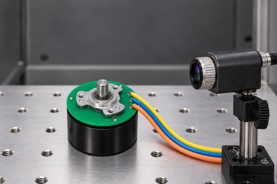
An optical surface measurement provides an external temperature reference, not a direct magnet reading. The stationary, unpowered arrangement shown illustrates sensor planning; operating measurements need a validated thermal correlation.
Direct magnet temperature measurements are valuable where an approved test arrangement permits them. However, instrumentation on a rotating assembly introduces additional mechanical and measurement challenges.
Any rotating instrumentation must be designed for its operating speed and mechanical environment. Unsecured sensors or cables must not be introduced into the rotating assembly.
Where direct measurement is impractical, a thermal model can estimate magnet temperature using measured losses, material properties, geometry, and heat-transfer conditions.
Model predictions should be compared against accessible temperature measurements under representative operating conditions. Agreement at one location alone does not establish accuracy throughout the rotor.
- Sensor calibration: Verify accuracy over the intended measurement range and document relevant calibration uncertainty.
- Sensor location: Identify the exact measurement position and its thermal relationship to the magnets.
- Response time: Confirm that instrumentation can capture meaningful changes during transient heating.
- Model validation: Compare calculated and measured temperatures across relevant loads and operating states.
- Worst-case estimation: Include defensible allowances for thermal gradients, operating variation, and uncertainty.
The resulting temperature estimate should identify the magnet location, operating condition, calculation basis, and uncertainty. This becomes an essential input to the demagnetization assessment.
Which Other Motor Components May Restrict the Trial Temperature?
Magnet stability does not establish the thermal capability of the complete motor. Other components can reach their own functional or structural limits before irreversible magnet degradation occurs.
Each relevant component should be assessed using its actual local temperature and operating environment, rather than applying one temperature limit to the entire assembly.
- Magnet adhesives and retention: Verify bonding material compatibility, thermal aging behavior, and mechanical retention under operating loads and temperature exposure.
- Protective coatings: Review coating temperature compatibility, adhesion, and resistance to the environmental conditions expected during testing.
- Bearings and lubricants: Consider lubricant performance, bearing materials, thermal expansion, and the mechanical loading experienced during operation.
- Hall sensors and electronics: Check applicable component temperature limits and possible effects on sensing accuracy, signal reliability, and commutation.
- Winding insulation and wiring: Evaluate insulation temperature capability, connection integrity, conductor heating, and relevant thermal aging mechanisms.
An adhesive restriction, for example, may govern the trial even when the magnets themselves remain magnetically stable. Magnet retention also requires appropriate mechanical verification.
Electronic components require separate attention because electrical behavior can change before permanent damage occurs. Temperature-dependent sensor errors may affect commutation and motor performance.
Gian Transmission provides custom BLDC motor configurations involving electrical parameters, motor structures, and control options. Component-level temperature requirements should be reviewed for the selected design.
The approved trial envelope must satisfy all relevant component restrictions. A favorable magnet assessment cannot override a lower allowable temperature elsewhere in the motor.
How Should Engineers Establish Approved Trial Limits?
Before heating begins, the engineering team needs a documented operating envelope based on material evidence, magnetic analysis, temperature assessment, and component restrictions.
This envelope should distinguish normal operating conditions from temporary test exposure and prohibited conditions. The categories must reflect the intended application and approved test scope.
Define the Trial Operating Envelope
Start with the relevant magnet demagnetization analysis and establish the estimated magnet temperatures associated with each proposed operating condition.
Next, compare these conditions against adhesive, bearing, electronic, insulation, and other applicable restrictions. The most restrictive verified requirement may govern the permitted exposure.
Engineering margin should account for uncertainty in material data, magnetic modeling, temperature measurement, manufacturing variation, and the expected operating duty.
No universal numerical margin is appropriate for every motor. Its value and justification must be reviewed against the specific design and available evidence.
Where uncertainty is too large to support a confident decision, improve measurement quality, obtain additional material information, or reduce the proposed exposure.
Set Monitoring Requirements and Test Termination Conditions
Engineers should specify the conditions requiring test suspension or termination before any thermal exposure begins. Relying on operator judgment after abnormal behavior appears can lead to inconsistent or excessive exposure.
- Temperature limits: Define allowable measured temperatures and estimated magnet temperatures for each trial stage.
- Electrical limits: Establish permitted phase currents, operating voltage conditions, and controller restrictions.
- Mechanical limits: Specify acceptable operating speed, load, vibration behavior, and any relevant retention restrictions.
- Exposure limits: Define permitted dwell durations, thermal stabilization requirements, and progression conditions.
- Abnormal conditions: Identify events requiring immediate shutdown, suspension, inspection, or engineering review.
Warnings may prompt additional observation, while predetermined critical conditions require stopping the test. The distinction should be explicit in the approved procedure.
The test plan should identify responsible personnel, monitoring equipment, data collection requirements, and the authority needed to approve progression between stages.
How Should Engineers Conduct a Controlled Hot-Environment Trial?
A staged test helps separate temperature effects from changes caused by electrical loading, mechanical conditions, or instrumentation. Each testing phase requires documented conditions for starting, progressing, and confirming successful completion.
Use guarded equipment, suitable instrumentation, and approved operating procedures. The trial must remain within verified electrical, thermal, and mechanical boundaries.
Record Baseline Performance Before Heating
Establish the motor’s initial condition at a controlled reference temperature. This creates a repeatable basis for evaluating any persistent performance change after hot exposure.
Open-circuit back-EMF is particularly useful because its voltage-speed relationship reflects the effective magnetic flux linkage under defined measurement conditions.
Drive the motor mechanically at a controlled speed with its winding terminals safely isolated from the active drive, using a suitable approved test arrangement.
Measure and record the selected line-to-line back-EMF quantity, waveform, and speed. The measurement definition must remain unchanged during later comparisons.
The reference condition should include sufficient thermal stabilization, consistent wiring, and documented instrument settings. Repeat measurements where needed to characterize baseline variability.
Conduct the Trial in Controlled Stages
Begin with an environmental soak that allows relevant temperatures to approach the defined starting condition. Confirm that monitoring channels operate correctly before powered testing.
Introduce electrical loading progressively, using approved operating points rather than immediately applying the maximum anticipated duty.
At each stage, observe whether temperatures are stabilizing, continuing to rise, or responding unexpectedly to changes in motor load.
Transient conditions deserve particular attention because brief current peaks and delayed rotor heating may create stresses not represented by steady-state measurements.
| Trial Stage | Monitored Parameters | Evidence and Progression Criteria |
| Reference baseline | Temperature, speed, back-EMF | Repeatable baseline and documented measurement configuration |
| Environmental soak | Ambient and accessible motor temperatures | Specified thermal condition reached without abnormal behavior |
| Initial powered operation | Current, speed, temperatures, vibration | Stable behavior within approved operating limits |
| Intermediate loading | Thermal response and electrical loading | Measured response consistent with approved expectations |
| Representative maximum duty | Worst relevant current, temperature, and load | Exposure completed without violating defined stop criteria |
| Controlled shutdown and cooling | Cooling history and abnormal indications | Safe return to the established reference condition |
| Post-trial verification | Back-EMF, speed, temperature, instrument condition | Comparison completed against application-defined acceptance criteria |
Proceed to the next stage only when the required evidence supports continued testing. An unresolved measurement anomaly should not be treated as successful completion.
If temperatures exceed approved boundaries, current behaves unexpectedly, or mechanical instability develops, follow the predetermined stop procedure and preserve the recorded data.
After the planned exposure, shut down according to the approved procedure. Record relevant cooling behavior and avoid assuming that immediate external cooling represents the rotor’s thermal history.
How Can Engineers Check for Magnet Performance Changes After Cooling?
Post-trial verification determines whether the motor exhibits a persistent performance difference after returning to a controlled reference condition. It should not rely on measurements collected at unmatched temperatures.
Back-EMF provides useful evidence because permanent changes in effective rotor magnetic flux may affect generated voltage at a given speed.
However, a back-EMF difference alone cannot establish that irreversible magnet demagnetization occurred. Several electrical, thermal, mechanical, and measurement factors can produce misleading comparisons.
Repeat Back-EMF Measurements Under Matched Conditions
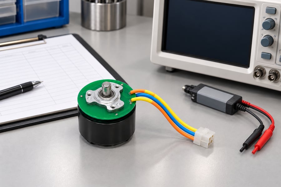
Prepare the measurement definitions and instrument configuration before comparing cooled back-EMF results. This unpowered equipment layout illustrates preparation, rather than a running test or a specified connection diagram.
Allow the motor to return to the baseline reference temperature and achieve the required thermal stability before performing the post-trial measurement.
Use the same winding terminals, measurement configuration, mechanical drive arrangement, and voltage measurement definition wherever practical.
Control actual rotor speed rather than relying exclusively on a command value. A speed difference can directly affect measured back-EMF amplitude.
For sinusoidal measurements, distinguish RMS voltage from peak amplitude. Different waveform-processing methods can create apparent changes unrelated to magnet performance.
- Speed: Measure actual rotor speed and normalize comparisons only when the measurement model supports that approach.
- Temperature: Confirm matching reference temperatures and sufficient stabilization before comparing results.
- Wiring: Verify winding connections, selected terminal pairs, continuity, and measurement polarity.
- Instrumentation: Check calibration, probe configuration, bandwidth, and measurement repeatability.
- Waveform analysis: Apply consistent RMS, peak, or fundamental-component definitions throughout the comparison.
Back-EMF comparisons should also account for waveform shape. An apparent change in one measured quantity may reflect altered processing rather than reduced magnetic flux.
If baseline and post-trial measurements were obtained under different operating conditions, resolve those differences before making any claim about magnet degradation.
Investigate Any Persistent Performance Difference
A repeatable reduction in back-EMF after cooling may indicate reduced effective magnetic flux linkage. It is a reason for investigation, not definitive proof of irreversible demagnetization.
First determine whether the observed difference exceeds the established measurement repeatability and combined uncertainty of the comparison.
Next, examine possible changes in rotor speed, temperature, wiring connections, measurement equipment, and electrical or mechanical configuration.
A genuine persistent difference may still have causes other than magnet material degradation, including mechanical displacement or other changes affecting effective magnetic flux linkage.
Where uncertainty remains, additional magnetic inspection, suitable electrical characterization, or approved component-level evaluation may be required to identify the underlying mechanism.
The engineering interpretation should distinguish confirmed observations, plausible explanations, and conclusions supported by further evidence. Do not equate every performance deviation with permanent magnet damage.
Document Results and Engineering Approval
A useful trial record connects the selected materials, approved operating envelope, measured exposure, and final performance assessment in one traceable engineering package.
Material evidence should identify the magnet specification and relevant temperature-dependent magnetic characteristics used in the analysis.
The magnetic assessment should document the load-line assumptions, relevant opposing fields, worst-case operating conditions, and remaining uncertainties.
Thermal records should identify sensor locations, calibration status, model correlations, estimated magnet temperatures, and the actual time-temperature history.
Test records must include operating stages, electrical loading, stop events, deviations, cooling conditions, and matched before-and-after back-EMF measurements.
Compare these findings against application-defined acceptance criteria. Any unresolved performance difference or restriction should receive explicit engineering disposition before further exposure.
The final deliverables should be an approved motor configuration, verified material and component evidence, documented magnetic and thermal analyses, complete test records, defined operating restrictions, and signed engineering acceptance.