
Stationary stator leads in an enclosed outrunner BLDC motor must follow fixed structures and remain outside the rotating assembly’s full swept envelope. The correct path depends on the actual shaft, support, and enclosure arrangement, not a presumed motor architecture.
Engineers must establish clearance, retention, electrical integrity, and assembly controls, then validate the completed routing under representative operating conditions.
Which Outrunner Motor Components Are Stationary and Which Rotate?
Identify the Actual Mechanical Architecture
An outrunner brushless DC motor has an internal stator surrounded by an external rotor carrying permanent magnets. This construction influences mechanical clearance, electrical connections, and enclosure integration.
The stator remains stationary relative to its mounting structure, while the outer rotor rotates around it. However, shaft connections and supporting arrangements can differ between motor designs.
Some assemblies use a rotating shaft connected to the rotor bell. Others incorporate stationary shaft or support arrangements with different bearing and mounting configurations.
Engineers should therefore inspect the actual assembly drawing before deciding where cables can pass. Shaft appearance or motor category alone cannot establish whether a particular surface rotates.
Gian Transmission offers configurable outrunner brushless DC motors with different mechanical integration options. The selected assembly geometry determines which structures can safely support stationary wiring.
A separate protective enclosure may remain stationary while the rotor bell turns inside it. The stationary enclosure must not be confused with the rotating outer motor housing.
The drawing should identify the rotor, stator support, shaft, bearing interfaces, mounting features, protective covers, and electrical exit locations. Each component needs a confirmed motion classification.
Establish the Permitted Lead Path
Stator winding leads must remain attached to stationary structures throughout their route toward the external controller. No section may enter the swept region of a rotating component.
Routing through a rotating shaft, rotor bell, or rotating cover is unsuitable for ordinary stationary leads. Such arrangements would expose connections to twisting or repeated mechanical interference.
A hollow support can provide a cable passage only when its stationary function is explicitly established by the design. Its internal geometry must also protect the conductors.
The permitted route should be marked directly on the assembly drawing. This establishes a common reference for motor design, harness preparation, enclosure manufacturing, and installation inspection.
How Should Engineers Establish a Safe Lead-Routing Envelope?
Define the Complete Rotating Envelope
A safe routing envelope describes the space stationary conductors may occupy without contacting rotating components. It must account for more than the nominal dimensions shown in CAD.
Identify every rotating feature near the proposed harness route, including the rotor bell, shaft sections, fasteners, adapters, and attached mechanical components.
Radial runout can shift a rotating surface toward a nearby conductor during operation. Bearing clearances, component tolerances, and mounting conditions can influence the resulting movement.
Axial endplay also matters, particularly near rotor end faces and shaft-mounted components. The assessment must include permitted axial movement under relevant operating loads.
Thermal expansion changes component dimensions as the motor and enclosure heat up. Different materials and temperature distributions can alter the available clearance between stationary and rotating parts.
Vibration and structural deflection introduce further movement. A harness that clears the rotor during static inspection may shift toward it when subjected to operating excitation.
Determine Application-Specific Clearances
Clearance calculations should consider the combined dimensional and movement allowances associated with both the rotating assembly and the stationary harness.
Harness tolerance includes cable outside diameter, sleeve thickness, clamp positioning, installation variation, and possible deflection between supports. Nominal cable centerlines are insufficient for determining clearance.
Engineers should evaluate credible worst-case relative positions rather than simply adding every independent maximum without justification. The tolerance method must reflect actual assembly relationships.
Where the clearance changes around the circumference, inspect the most restrictive region. Local projections and rotor fasteners may create greater interference risks than smooth surfaces.
The required clearance depends on geometry, motion, material behavior, and operating conditions. A single universal clearance value cannot represent every enclosed outrunner configuration.
The following assessment identifies the mechanical information needed before approving a stationary lead path.
| Component or Interface | Relevant Movement or Tolerance | Required Verification |
| Rotor bell | Radial runout, dimensional variation, thermal growth | Evaluate maximum swept diameter against the harness boundary |
| Shaft and adapters | Rotation, radial movement, axial endplay | Confirm shaft function and worst-case movement envelope |
| Bearings and supports | Internal clearance, deflection, mounting variation | Review permitted movement under operating loads |
| Stationary harness | Cable diameter, clamp position, bending, vibration | Verify the complete retained harness envelope |
| Enclosure | Assembly tolerance, thermal expansion, structural movement | Confirm relative position after final installation |
| Fasteners and projections | Local protrusions, positional tolerances | Check minimum local clearance throughout rotation |
The resulting clearance assessment should identify the governing dimensions, allowable movement, and inspection conditions. Any unresolved interface needs design clarification before harness routing is approved.
How Should Stationary Leads Be Anchored and Mechanically Protected?
Establish Fixed Anchoring and Strain Relief
Stationary leads require mechanical support that prevents movement toward rotating components. The anchoring arrangement should also protect winding terminations from external pulling forces.
The first support point is particularly important because movement near the stator exit can transfer bending or tensile loads directly into electrical connections.
Anchors must attach to structures confirmed as stationary. A clamp mounted on a rotating component cannot safely retain an ordinary fixed stator harness.
Available retention methods include fixed clips, cable clamps, dedicated channels, and other approved supports. Selection depends on harness construction, mounting geometry, and operating conditions.
Clamp compression requires attention. Excessive force can damage conductor insulation, while insufficient retention may allow gradual cable movement under vibration.
Strain relief should control external pulling loads without imposing excessive stress on conductors. Connector retention alone may not provide adequate protection for internal winding connections.
Manage Cable Bending and Mechanical Protection
Each cable has bending limitations determined by conductor construction, insulation, shielding, and intended movement. Use the bend radius limits specified for the selected cable construction to prevent excessive mechanical stress during installation.
Routing should avoid forcing conductors around sharp housing corners or through openings that compress their insulation. Protective sleeves cannot compensate for fundamentally unsuitable geometry.
Any required service loop must remain entirely within the approved stationary envelope. Its maximum possible position matters more than its appearance during initial installation.
Service loops provide installation or maintenance flexibility, but unsupported excess length can create vibration problems. Fixed capture points should prevent loops from approaching rotating components.
Harness supports should distribute loads appropriately and avoid concentrated bending near terminals. The design must also allow cables to accommodate expected stationary-structure thermal movement.
Wire protection should address foreseeable contact with stationary edges, assembly tools, and neighboring components. Routing must remain mechanically secure without relying on insulation abrasion resistance.
How Should Stationary Leads Pass Through the Motor Enclosure?
Choose an Appropriate Cable Exit on a Fixed Enclosure
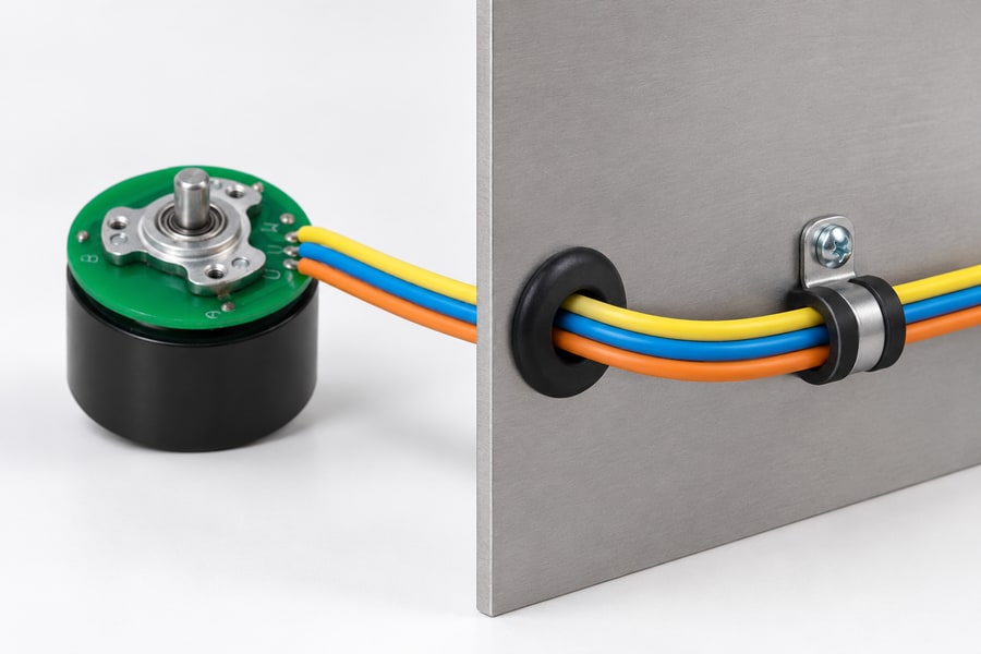
A protected panel opening and a separate cable restraint perform different functions. This illustrative panel sample shows the distinction; actual routing and pull-out requirements come from the enclosure and harness drawings.
The enclosure exit must provide a continuous stationary path from the internal stator wiring to the external electrical connection. Its location should support the approved internal route.
Fixed housing openings, grommets, cable glands, and dedicated passages offer different mechanical and environmental functions. The appropriate choice depends on the enclosure’s specific geometry, mounting arrangement, and required protection.
A grommet primarily protects cable insulation from the opening edge and may provide limited sealing depending on its design. It does not automatically provide strain relief.
A cable gland may provide sealing, cable retention, or both when correctly selected and installed. Its specific functions must be confirmed rather than assumed.
Mechanical strain relief and environmental sealing should be evaluated as separate requirements. A sealed entry can still transmit damaging pulling forces to internal conductors.
The entry must also accommodate the selected cable diameter and jacket construction. Excessive compression, unsuitable opening dimensions, or sharp transitions can compromise long-term integrity.
Address Environmental and Thermal Conditions
An enclosed motor is not necessarily waterproof. Its environmental performance depends on enclosure joints, cable entries, materials, installation orientation, and other relevant interfaces.
Any required ingress protection must be defined and verified for the complete assembly. An enclosure’s appearance does not establish a particular IP classification.
Thermal conditions also require attention because winding heat can raise nearby cable temperatures. The actual conductor location may experience temperatures different from the external housing surface.
Insulation, sleeves, grommets, and gland materials should be selected according to expected temperature exposure and environmental conditions, including any relevant chemical or contamination risks.
Enclosure geometry can influence cooling airflow and local temperature distribution. Thermal verification should reflect the final installed configuration rather than an unrestricted motor arrangement.
Protective components must not obstruct required cooling paths or introduce contact with rotating parts. Environmental protection and thermal management therefore require coordinated mechanical design.
How Should Phase Leads and Hall Sensor Wiring Be Routed?
Arrange Power and Sensor Conductors
Phase leads carry the electrical current used to energize the stator windings. Their conductor size, insulation, and termination design must suit the intended operating conditions.
Hall sensor wiring carries lower-level position information used by compatible controllers. These signals can be affected by electrical interference associated with motor switching.
Physical separation between phase conductors and sensor wiring can reduce some coupling mechanisms. However, separation alone does not guarantee reliable Hall signal operation.
Shared cable passages, connector arrangements, and return conductors can still introduce interference. Engineers must examine the complete electrical interface rather than conductor spacing alone.
Where practical, conductor arrangement should avoid unnecessary parallel runs between sensitive sensor wiring and high-current switching paths. The final routing depends on available enclosure space.
Connectors must maintain correct phase identification, Hall supply connections, signal assignments, and return paths. Wiring documentation should correspond directly to the controller interface.
Control Signal Integrity
Hall signal reliability depends on the sensor supply, return-current paths, grounding arrangement, input thresholds, and electrical characteristics of the connected controller.
A poorly arranged return path can create voltage disturbances even when signal conductors are physically separated from phase cables. Shared impedance deserves particular attention.
Shielding may help selected installations, but its effectiveness depends on cable construction, termination, and grounding strategy. Shielding should follow an evaluated interface design.
Controller input conditioning, appropriate filtering, and suitable pull-up arrangements may also be necessary. These measures must remain compatible with the sensor output and timing requirements.
Gian Transmission’s custom brushless DC motor configurations provide a relevant basis for reviewing electrical parameters and control-interface requirements during integration planning.
Electrical validation should include representative switching conditions, speed changes, and operating loads. Inspect Hall waveforms for disturbances that could affect position interpretation.
Correct mechanical routing therefore requires corresponding electrical verification. A harness can remain safely outside the rotor envelope while still exhibiting unacceptable signal behavior.
How Can Enclosure Assembly Preserve the Approved Lead Route?
Prevent Wire Displacement During Closure
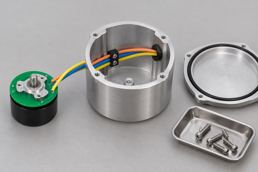
Review the cable path with the lid removed, then verify it again after closure. The separate enclosure sample illustrates clearance planning and does not specify the motor mounting or sealing performance.
Enclosure installation can alter cable positions even when the internal routing initially meets its clearance requirements. Assembly procedures must preserve the approved harness arrangement.
The installation sequence should establish when the stator, wiring supports, connectors, and enclosure components are positioned. Each operation must avoid displacing previously secured conductors.
Before closure, technicians should confirm that cables occupy their intended channels and retained positions. Temporary assembly handling must not leave unsupported loops near the rotor.
Housing lids and mating surfaces can trap insulation if cables cross unintended interfaces. Fasteners may also displace wires when clearance around their installed positions is inadequate.
Seal compression creates another potential movement source. The enclosure design should prevent seals or closing surfaces from pushing the harness toward rotating components.
Assembly access must allow personnel to position conductors correctly without excessive force. Routing that cannot be reproduced reliably introduces avoidable manufacturing and maintenance variation.
Establish Repeatable Closure Inspection
Inspection points should be defined before access becomes restricted. Technicians need an approved method for confirming correct routing and enclosure readiness.
Useful inspection references include fixed cable positions, visible retention features, prescribed harness orientations, and controlled closure steps. These reduce dependence on individual installer judgment.
When internal clearance cannot be observed after closure, engineers should establish an appropriate indirect verification method or inspectable assembly features before approving production procedures.
Maintenance instructions should identify which enclosure operations require renewed routing checks. Cable replacement, connector service, or lid removal can disturb previously accepted positions.
A repeatable inspection method must verify the completed assembly configuration, not merely the loose harness. Final acceptance still requires checking the assembled motor’s mechanical behavior.
How Should Lead Routing Be Validated Under Operating Conditions?
Verify Mechanical and Electrical Integrity
Validation begins with the completed routing design and controlled assembly procedure. Engineers should establish test conditions, acceptance criteria, and inspection responsibilities before testing.
Approved de-energized rotation checks can identify obvious interference between stationary leads and rotating components. These checks must follow suitable mechanical safety procedures.
Rotation checks should cover relevant rotor positions and accessible regions, including areas near fasteners, shaft features, and rotor end faces.
Electrical verification should examine conductor continuity, insulation integrity, connector retention, and appropriate separation between circuits. Test methods must suit the installed electronics.
Insulation testing requires particular care when Hall sensors or controller electronics remain connected. Test voltages and connections must follow approved component-specific procedures.
Mechanical clearance and electrical continuity answer different questions. Passing an electrical check does not demonstrate that the harness will remain outside the rotating envelope.
Verify Lead Routing Under Actual Operating Conditions
A stationary clearance check alone cannot confirm that the harness will remain secure throughout the motor’s specified operating range. Representative-duty testing should evaluate the combined effects of rotation, electrical loading, temperature, and vibration.
Testing must use appropriate guarding, approved operating limits, and suitable observation methods. Exposed rotating outrunner components must not be approached during powered operation.
The test sequence should cover relevant operating speeds, acceleration conditions, load changes, and thermal states. These conditions influence both mechanical movement and electrical behavior.
Where the application includes repeated starting or reversing, those events should be represented when approved. Dynamic loading may reveal movement not apparent during steady operation.
Temperature stabilization matters because housing growth and cable flexibility can change with operating temperature. Cold and warm conditions may produce different clearance relationships.
Vibration should be evaluated for its potential to loosen retention features or move unsupported conductors. Particular attention is needed near clamps and cable entry transitions.
Following powered testing, inspect accessible conductors and supports for abrasion, compression, insulation damage, discoloration, or movement from their original positions.
Hall signal verification should assess operation under representative switching conditions. Unexpected position transitions or intermittent behavior require investigation of wiring, returns, and interface conditioning.
Where environmental protection is required, sealing performance needs separate verification. Successful motor operation does not independently establish enclosure resistance to moisture or contamination.
Any failed check should trigger documented investigation and corrective action. Revised harness geometry or retention arrangements must be reassessed against the original clearance requirements.
Record Final Engineering Acceptance
Acceptance criteria should connect each routing requirement with an appropriate verification method. The evidence must represent the actual motor, enclosure, and harness configuration.
The following table provides a practical framework for recording design checks, assembly verification, and representative operating tests without assuming universal acceptance limits.
| Inspection or Test | Verification Method | Application-Defined Acceptance Criteria | Required Records |
| Component motion identification | Review assembly drawings and mechanical interfaces | All stationary and rotating components correctly identified | Approved assembly drawing |
| Routing clearance | Tolerance analysis and mechanical inspection | Required clearance maintained across the defined movement envelope | Clearance calculations and inspection results |
| Harness retention | Inspect support positions and perform approved retention checks | Specified anchoring and strain relief requirements satisfied | Harness drawing and retention inspection record |
| Enclosure closure | Controlled installation and final-position inspection | No trapped conductors or unacceptable routing displacement | Assembly inspection record |
| Electrical integrity | Approved continuity, insulation, and signal checks | Application electrical requirements satisfied | Electrical test results |
| Representative operation | Guarded speed, load, temperature, and vibration testing | No unacceptable cable movement, damage, or signal faults | Operating conditions and test observations |
| Environmental protection | Application-specific sealing verification where required | Defined environmental protection requirements satisfied | Environmental verification records |
Test documentation should distinguish directly measured results from engineering assessments. Where clearances rely on calculations, record the assumptions, input tolerances, and supporting measurements.
Inspection evidence should identify the tested configuration and relevant revision levels. Changes to cable construction, enclosure geometry, or mounting arrangements may require additional verification.
Final engineering approval should include the assembly drawing identifying fixed and rotating structures, approved lead-routing drawing, clearance analysis, harness specifications, and cable-entry requirements.
The completed handover should also contain anchoring details, assembly and reassembly instructions, inspection criteria, electrical verification results, representative-duty test records, and application-specific acceptance approval.