
Separating cogging torque from powered ripple begins with unpowered shaft torque plotted against rotor angle. An ideal slotless BLDC motor has no conventional tooth-related cogging, so residual patterns require investigation.
Then measure powered torque, phase currents, and rotor angle simultaneously. OEM engineers can use controlled comparisons to distinguish magnetic detent effects, mechanical drag, and current-dependent disturbances before proposing design changes.
What Distinguishes Cogging Torque from Powered Torque Ripple in a Slotless BLDC Motor?
Why an Ideal Slotless Stator Has No Conventional Cogging Torque
In a slotted motor, rotor magnets encounter changing magnetic reluctance as they pass stator teeth. That interaction produces position-dependent cogging torque even when no phase current flows.
An ideal slotless stator removes the tooth-and-slot geometry responsible for this conventional effect. It does not remove bearings, magnetic asymmetry, eccentricity, or every possible source of unpowered periodic torque.
Call a repeatable unpowered magnetic disturbance residual detent torque until its origin is established. Calling every low-speed bump “cogging” can send an OEM team toward unnecessary stator redesign.
- Magnetic possibility: Rotor or magnet asymmetry may produce a position-locked disturbance without stator slots.
- Mechanical possibility: Bearings, couplings, and fixture alignment can produce periodic or direction-dependent resistance.
- Measurement caution: An angle-locked waveform alone cannot prove that magnetic forces caused it.
What Changes When the Motor Is Powered?
Powered torque is produced by winding currents interacting with the rotor magnetic field. Its instantaneous value can vary with back-EMF harmonics, current distortion, commutation behavior, and position estimation.
Even a nearly featureless unpowered trace can accompany noticeable energized ripple. Conversely, a small unpowered detent component may remain visible within a larger current-dependent waveform.
For the OEM decision, separate the questions: what resists shaft rotation without commanded current, and what torque variation appears during the specified powered operating condition?
Residual detent torque is associated with magnetic potential energy and rotor position; powered ripple describes variations while electrical torque is generated. Similar-looking plots do not imply identical physics or corrective actions.
The brushless DC motor category provides product context, but slotless construction and electrical parameters must be confirmed for the individual design being evaluated.
How Should You Set Up a Reliable Torque Measurement Test?
Choose Sensors That Preserve Small Torque Variations
Match the torque transducer range to the expected mean load and disturbance amplitude. Excessive range may hide small variations; inadequate capacity can overload the instrument during starts or transients.
Record accuracy, resolution, calibrated range, noise floor, and usable bandwidth separately. A sensor can report average torque accurately yet fail to resolve a narrow commutation-related feature.
Measure rotor position with a repeatable mechanical reference. If the rotor has p pole pairs, electrical angle equals p × mechanical angle plus an offset, with all angles expressed in the same angular unit.
Check the full acquisition chain, not just the sensor datasheet. Filtering can reduce a narrow peak, and unmatched channel delays can make a torque event appear disconnected from its associated current transition.
- Timing: Use a shared acquisition clock or verified timestamp alignment for torque, encoder, and current channels.
- Bandwidth: Capture the relevant harmonic content without aliasing, while documenting analog and digital filters.
- Calibration: Confirm torque zero, transducer polarity, encoder direction, and current-sensor polarity before collecting comparisons.
Control Fixture Drag, Compliance, and Temperature
A low-disturbance motor can appear rough if the drive fixture contributes torque pulsations. Coupling eccentricity, bearing preload, cable forces, and shaft misalignment all deserve a baseline check.
Where practical, characterize the external drive and coupling without the test motor or with a suitable reference assembly. Record what the baseline includes rather than assuming every fixture effect can be subtracted.
Keep the mounting orientation, coupling stack, sensor position, and winding temperature traceable. Thermal expansion changes preload; warm bearings and cold bearings may not produce identical drag.
For powered testing, the torque measured at the shaft can include effects of load inertia and mechanical compliance. A resonance may magnify a small excitation, so a large sensor signal need not mean large air-gap torque ripple.
| Measurement Channel | Unpowered Test | Powered Test | Principal Check |
| Shaft torque | Low-speed reaction torque | Mean torque and ripple | Calibration, bandwidth, overload margin |
| Rotor encoder | Mechanical-angle reference | Angle and speed | Direction, index stability, timing |
| Phase current | Confirm negligible excitation | Actual winding-current waveform | Offset, polarity, sampling alignment |
| Temperature | Initial and final condition | Operating thermal state | Comparable bearing and winding conditions |
| Fixture baseline | Drag and periodic artifacts | Dynamic and load-dependent artifacts | Repeatability after remounting |
How Do You Measure Residual Unpowered Torque?
Step 1: Remove Excitation and Document Terminal Conditions
Disable the motor drive and verify that no commanded phase current remains. For an unpowered magnetic-detent assessment, open-circuit winding terminals are generally preferable to unintentionally shorted phases.
Shorted windings can carry induced currents when the rotor turns, creating electromagnetic braking that depends on speed. Open circuits can still leave small parasitic effects, so state the connection explicitly.
Check that the external rotation system cannot backfeed the controller through an unintended path. Record the winding connection, controller isolation method, ambient condition, and initial motor temperature.
Electrical isolation should be verified rather than inferred from a disabled command. An attached inverter, protection network, or measurement probe may leave a conduction path that alters the baseline during external rotation.
- Safety: Use an appropriate isolation procedure before changing terminal connections or rotating the shaft externally.
- Traceability: Identify the exact fixture and electrical state used for each saved waveform.
Step 2: Map Torque Against Mechanical Rotor Angle
Drive the shaft slowly through several complete mechanical revolutions at approximately constant speed. If torque is extremely small, a quasi-static angle-stepping method may help separate dynamics from position effects.
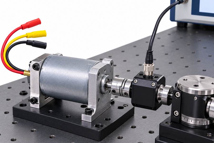
Illustrative external test arrangement; the image does not identify the stator construction of a specific motor.
Acquire torque and angle together, then repeat clockwise and counterclockwise. Use a consistent sign convention so reversal does not accidentally invert the apparent magnetic component during comparison.
Discard acceleration and stopping intervals when estimating steady-position effects. An accelerating rotor requires inertial torque; that contribution is not evidence of cogging or detent torque.
If the drive speed fluctuates, inspect whether apparent torque peaks coincide with those fluctuations. Repeating the scan more slowly or by stationary angular increments helps challenge an inertia-related explanation.
Illustrative example: A narrow feature appears near the same mechanical angle on repeated revolutions. That reproducibility justifies investigation, but does not yet identify whether the motor or fixture generated it.
Step 3: Test Whether the Pattern Is Magnetic, Frictional, or Artificial
Friction generally opposes motion, so its contribution changes sign when rotation reverses. A conservative magnetic position-dependent torque, expressed under one physical torque convention, does not reverse merely because travel direction changes.
Comparing aligned forward and reverse traces can therefore help separate direction-even and direction-odd components. It is only an estimate when friction exhibits stick-slip, hysteresis, or speed dependence.
- Direction comparison: Look for offsets that follow motion direction rather than absolute rotor position.
- Speed comparison: Repeat at another low speed to expose viscous losses, eddy-current effects, or dynamic artifacts.
- Fixture comparison: Recheck alignment or remount the assembly to see whether a periodic feature moves or changes.
- Magnetic attribution: Reserve that label for a persistent position-dependent component supported by independent checks.
The result of this stage is an unpowered disturbance map, not automatically a measured cogging-torque specification. Preserve its direction, speed, temperature, and uncertainty metadata.
How Do You Measure Powered Torque Ripple Under Controlled Conditions?
Step 1: Choose Operating Points from the OEM Duty Cycle
Define the intended shaft speed, load torque, bus voltage, control mode, and thermal state before turning on the motor. A single no-load run cannot represent a loaded motion axis.
Include low-speed points when smooth indexing or stable positioning matters, and representative loaded points when pulsation may excite the mechanical system. Keep each test condition reproducible.
Illustrative example: An axis shows vibration only while holding a particular loaded speed. Test near that operating point, rather than treating a high-speed no-load waveform as decisive evidence.
Step 2: Capture Torque, Rotor Angle, and Actual Phase Currents Together
Collect shaft torque, rotor angle, speed, and measured phase currents on a synchronized time base. Current commands alone are insufficient: actual winding currents can lag, distort, or saturate.
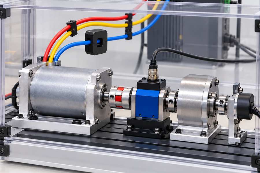
Illustrative external test arrangement; the image does not identify the stator construction of a specific motor.
Preserve several stable mechanical revolutions and retain raw samples. Inspect synchronization delay, encoder interpolation, torque-channel phase shift, and anti-alias filtering before calculating ripple magnitude.
Resampling by angle is useful for order analysis, but it changes the representation of noise and nonstationary events. Retain the original time series to investigate switching transients or speed-control oscillations.
- Electrical reference: Determine the pole-pair count and rotor electrical-angle offset for the tested assembly.
- Mechanical reference: Record where the torque sensor sits relative to couplings, load inertia, and supporting bearings.
- Analysis window: Use a stationary operating interval rather than mixing startup, acceleration, and steady running.
The brushless DC motor driver information can frame controller-related review questions; actual switching, commutation, sensing, and current-loop settings must be documented for the tested drive.
Step 3: Change One Condition Deliberately
Repeat the test across specified load-current levels while controlling speed and temperature as closely as practical. Then examine speed changes, recognizing that bandwidth and resonance effects may also change.
When the control system permits, compare well-documented current-control or position-calibration settings. Changes in torque structure after a controller adjustment are clues, not immediate proof of causation.
Forward and reverse powered tests may expose asymmetric friction or control behavior. Do not compare raw signed traces without first normalizing shaft-torque and angle conventions.
How Can You Attribute the Measured Torque Variation to Its Source?
Align Angle-Referenced Waveforms Before Comparing Them
Convert time-domain torque signals into mechanical-angle coordinates using encoder data. Compare like angles, directions, and stable operating windows; do not visually align unrelated peaks by hand.
Separate the mean shaft torque from its fluctuating component within each defined powered test. State whether ripple is reported as peak-to-peak torque, RMS variation, or specified harmonic amplitude.
A peak-to-peak value equals the maximum measured torque minus the minimum over the stated analysis window, in newton-metres (N·m). Two traces can share this number while reaching their peaks at different rotor positions or arising from unrelated disturbances.
Illustrative example: A small unpowered feature recurs at one rotor angle, while a larger energized feature shifts with current-control settings. The comparison suggests two mechanisms requiring separate checks.
Use Mechanical and Electrical Order Analysis
Order analysis expresses periodic content in cycles per mechanical revolution. A feature at a fixed mechanical order may originate in the motor, coupling, load, or measurement fixture.
Electrical angle advances by one electrical cycle for each pole-pair passage, so an electrical fundamental occurs at p cycles per mechanical revolution for a motor with p pole pairs.
Current harmonics and torque harmonics can share order locations with mechanical disturbances. Match torque features against measured current and angle, then confirm findings with controlled changes.
- Angle locking: Repetition at the same encoder position establishes periodicity, not magnetic origin.
- Current correlation: A shared frequency or order supports further investigation; it does not alone establish torque causation.
- Phase behavior: Compare harmonic phase across operating points, preserving encoder zero and signal-processing delay.
Do Not Subtract Unpowered and Powered Peak-to-Peak Numbers
Peak-to-peak subtraction ignores when each disturbance occurs. Two waveforms of identical amplitude can reinforce at matching angles or partially cancel when their phase relationships differ.
The problem is deeper than arithmetic. Energizing a motor changes magnetic forces, bearing loads, current-induced heating, and operating dynamics; its friction and fixture responses may no longer match the baseline.
Angle-aligned waveform subtraction can sometimes estimate a component if the underlying conditions and transfer paths are comparable. Document that assumption and propagate measurement uncertainty before interpreting the residual.
For instance, removing an unpowered trace from a powered trace without accounting for speed-dependent fixture drag may create an apparent electromagnetic harmonic that is actually a test artifact.
When calculating any residual, preserve signed waveforms rather than subtracting magnitudes. Record the angle reference, interpolation method, operating-point mismatch, and the uncertainty of each contributing measurement.
Confirm Suspected Causes with Independent Changes
Assign each unexpected feature a hypothesis and a discriminating test. Repetition without a changed condition establishes consistency; it rarely establishes which component generated the disturbance.
| Observed Pattern | Possible Source | Verification Action |
| Unpowered, angle-locked variation | Residual detent torque or fixture geometry | Reverse direction and recheck the fixture |
| Direction-sensitive offset | Friction or hysteresis | Compare matched forward and reverse sweeps |
| Ripple changes with load current | Electromagnetic torque or altered mechanical loading | Compare current harmonics and thermal state |
| Disturbance near commutation events | Current distortion or position error | Inspect synchronized currents and rotor angle |
| Periodic feature changes after remounting | Coupling, alignment, or sensor artifact | Repeat baseline and powered tests |
| Ripple changes with speed | Dynamic resonance, drag, or control response | Use controlled speed sweeps and bandwidth checks |
Illustrative example: A torque harmonic weakens after encoder offset correction while measured current distortion also decreases. That supports a control-related explanation, pending repeat testing under unchanged load.
How Should OEM Engineers Specify and Validate Torque Smoothness?
Write Separate Unpowered and Powered Requirements
Specify unpowered residual torque using a defined angular range, rotation direction, speed or quasi-static method, and temperature. Avoid calling this value conventional cogging without evidence of its mechanism.
Define powered ripple at explicit speed, torque, voltage, temperature, and controller settings. State the statistic and bandwidth used to judge acceptance; limits should follow the application’s vibration and positioning needs.
A percentage relative to mean torque may help comparison under load, but it becomes unstable near zero mean torque. Use an absolute N·m criterion where percentage normalization would mislead.
Request Evidence That Can Be Reanalyzed
A short summary figure is not a complete qualification record. Request synchronized raw data, processed angle-referenced curves, analysis settings, and sufficient context to reproduce each result.
Repeatability should include separate runs and, when feasible, removal and reinstallation of the motor. A pass dependent on one carefully adjusted coupling position is weak evidence for production acceptance.
- Motor identity: Record model revision, verified stator construction, pole-pair count, shaft interface, and winding configuration.
- Operating conditions: Record voltage, speed, load, temperature, direction, and controller configuration for each run.
- Measurement chain: Record sensor calibration, encoder reference, sampling rate, filtering, alignment, and fixture baseline.
- Results: Provide unpowered maps, powered traces, harmonic spectra, repeat runs, and uncertainty estimates.
- Disposition: Identify unresolved patterns, proposed corrective actions, and the exact retest needed for acceptance.
Agree on a Model-Specific Engineering Handover
Gian Transmission lists custom brushless motor options, including a slotless design option and a 5V voltage category. Those category descriptions do not establish the construction or rating of any individual pictured model.
For an OEM review, confirm the selected design’s electrical parameters and mechanical interface before setting torque limits. Hold the controller setup fixed while assessing a motor revision; when testing a control change, retain the same motor and repeat the reference run.
Use the contact route to transmit a model-specific test brief when supplier coordination is required. The handover should contain approved operating points, terminal conditions, synchronized measurement requirements, waveform definitions, fixture controls, acceptance criteria, and an owner for every unresolved disturbance.