
A hollow shaft robot joint needs a validated cable path, not just a bore large enough for loose wires. Check connector passage, bend and torsion limits, strain relief, moving clearances, signal integrity, and replacement access across the full motion range. Then test the assembled harness through representative cycles with the covers and constraints in place.
An internal cable route can make a robot compact and protect wiring from external contact. It can also hide rubbing, connector stress, and accumulated twist until the system begins to fail intermittently. Treat the harness as a moving mechanical component as well as an electrical connection.
Why Is Bore Diameter Only the First Check?
The cable bundle must pass through the entire assembled joint, including bearings, sleeves, seals, covers, and sensor features. The narrowest or most awkward part of that route controls installation. A nominal shaft diameter says little about those local restrictions.
Include connectors and backshells in the model. A cable that fits comfortably may have a connector that cannot pass through the finished assembly. The resulting need to terminate wires after installation changes assembly labor, inspection access, and field replacement.
GIAN’s guide to hollow versus solid shaft harmonic drive motors covers the architecture decision. Harness validation is the next step: prove that the chosen internal path works throughout assembly, operation, and service.
Ask for the usable passage geometry when reviewing a harmonic drive motor. A sectional drawing or agreed keep-out model is more useful than a single headline bore dimension.
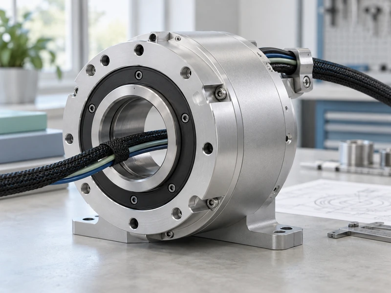
How Should Bending and Twisting Be Evaluated?
Use cable data for the actual motion type. A cable suitable for repeated bending is not automatically qualified for repeated torsion, and a static minimum bend radius is not necessarily a dynamic operating limit. Obtain the manufacturer’s conditions for the selected construction.
Trace where the bundle is fixed and where relative rotation is absorbed. A short free length between two restraints can concentrate twist, even when the overall robot has plenty of cable. The location and orientation of each restraint influence the strain distribution.
Evaluate the complete range of joint combinations. Two individually acceptable joint movements can create an unfavorable bundle shape when performed together. Check the motion path as well as the endpoint poses because an intermediate configuration may create the tightest bend.
For workmanship context, NASA’s cable and harness standard provides requirements for interconnecting assemblies, including installation-related practices. It does not establish fatigue life for a particular moving robot harness, and citing it does not make the robot or harness NASA-qualified.
Can a Hollow Shaft Support Unlimited Rotation?
The opening itself does not provide unlimited rotation for a cable crossing between stationary and rotating structures. Without an appropriate rotary interface or managed motion strategy, the cable can accumulate twist. Define whether the joint needs limited travel, multiple turns, or continuous rotation.
For limited travel, record the cable’s neutral condition and how assembly preserves it. A harness installed with initial twist may reach its permitted strain earlier in one direction. The robot’s calibration and motion limits should remain consistent with that installation condition.
If continuous rotation is required, evaluate the relevant rotary electrical, data, fluid, or optical interface. Its ratings and service needs become part of the actuator design. Do not treat a slip ring as interchangeable with a simple cable path, especially where signals have strict bandwidth or noise requirements.
The motor architecture can also affect the available route. When discussing BLDC motor shaft configurations, provide the required passage and motion constraints early. A motor that fits electrically may leave insufficient space for a maintainable harness.
Where Should Strain Relief Be Located?
Locate it so that cable movement is controlled without transferring repeated mechanical loading into the electrical termination. The connector, cable construction, and movement path determine the appropriate arrangement. Restraints should not crush insulation or force an abrupt bend immediately beside a rigid termination.
Check relative movement on both sides of each restraint. A clamp attached to a moving cover can behave differently from one attached to the joint structure. The harness drawing should show what each restraint is attached to and how the cable exits it.
Allow enough service length for the planned replacement procedure, but do not add loose loops without checking their path. Extra cable can rub against rotating parts, obstruct a sensor, or enter a pinch point. The goal is controlled movement, not simply more slack.
| Validation Item | Question to Resolve |
| Assembly passage | Can the finished harness and connectors be installed? |
| Motion path | Where are bending and twist concentrated? |
| Strain relief | Are terminations isolated from repeated cable loading? |
| Clearance | Can the bundle contact moving or sharp features? |
| Service access | Can the harness be replaced without damaging adjacent parts? |
How Can Wiring Affect Motor and Encoder Behavior?
Power conductors and sensitive feedback signals share a confined environment in many compact actuators. Routing, shielding, grounding, connector quality, and the drive’s installation requirements influence signal reliability. Follow the selected drive and sensor documentation rather than applying a universal wiring recipe.
Test with the motor operating, not only with continuity checked on a stationary bench. Electrical noise and motion-related contact faults may appear only during acceleration, loading, or certain cable positions. Record communication errors and encoder diagnostics alongside the mechanical test.
Distinguish a harness problem from a control problem. If an error follows a particular joint position or changes when the cable moves, inspect the cable path and terminations before changing gains. Keep changes controlled so that the actual cause remains identifiable.
GIAN’s article on thermal behavior inside robot actuators provides related packaging context. Heat near the harness can affect its operating conditions even when the electrical load on an individual wire is modest.
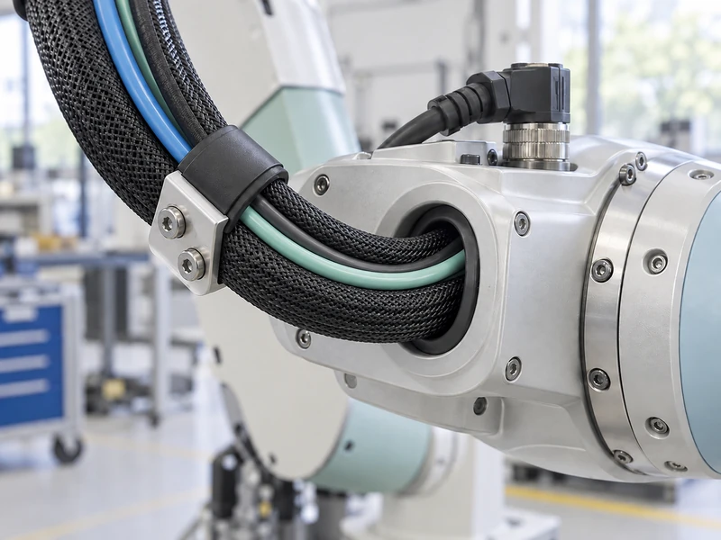
What Should a Harness Motion Test Include?
Use the actual cable construction, connector arrangement, restraints, covers, and internal surfaces wherever possible. A loose benchtop bundle does not reproduce the constraints inside the joint. Begin with slow observation of the full path before progressing to the intended motion cycle.
Record the installation state with photographs or drawings, including neutral position and restraint locations. Define the joint sequence, travel, speed, ambient conditions, electrical loading, and number of cycles. The resulting test is then reproducible after a cable or housing change.
Useful observations include:
- Changes in bend shape or accumulated twist.
- Contact with bore edges, fasteners, bearings, or rotating surfaces.
- Movement at connector backshells and restraints.
- Intermittent signal errors or continuity changes.
- Abrasion, jacket damage, or displaced shielding after inspection.
Use acceptance criteria appropriate to the actual cable and application. A completed cycle count is not a universal service-life claim, particularly if production cables, installation practices, or environments differ. Record the tested conditions and remaining qualification limits clearly.
What Should Be Checked After a Cable Replacement?
Verify the installed routing rather than assuming that a matching connector makes the replacement equivalent. Cable stiffness, jacket diameter, bend behavior, and connector exit geometry can differ between nominally similar parts. Those differences may alter the moving path inside the joint.
Confirm the neutral twist condition, restraint positions, and available travel before returning to the normal motion cycle. Check that covers do not push the bundle into an edge or reduce the space around a connector. The final closed assembly is the configuration that must pass.
Which Changes Require Another Motion Test?
Review any change to cable construction, bundle size, restraint location, bore protection, connector orientation, or joint range. The extent of retesting should follow the effect of the change, but a visual check alone may not resolve a new dynamic concern. Keep the reason for the chosen verification scope in the record.
For an illustrative service scenario, a thicker replacement cable might pass through the bore yet bend less freely near the rear cover. The joint could then place more force on a connector during reversal. A slow full-range observation would expose that behavior before the robot resumes its regular cycle.
Documenting the installed path also helps a technician reproduce the qualified configuration. Photographs, restraint dimensions, and a clear neutral-position instruction can prevent service work from unintentionally creating a new harness design.
How Should the Harness Be Included in the Actuator Specification?
Provide the bundle envelope, connector dimensions, cable motion ratings, joint travel, service procedure, and electrical interface requirements with the mechanical drawing. Identify who supplies and qualifies the harness and who controls any routing changes. This prevents the bore from becoming a late-stage compromise between separate teams.
GIAN’s preinstallation checks for geared motors can support the receiving stage, but a routed robot harness needs additional motion and signal testing after integration. Keep those acceptance stages separate in the project record.
A successful internal route remains installable, electrically reliable, and mechanically controlled through the intended task. Confirming that before the housing is finalized can prevent repeated cable failures and difficult service work. The hollow shaft is useful space only when the complete harness can use it reliably.