
A BLDC motor can be mechanically well designed and still perform poorly if the controller does not know the rotor position accurately enough.
A BLDC motor uses electronic switching for commutation instead of mechanical brushes. The controller must determine when to energize each phase according to rotor position. How that position is obtained has a direct effect on startup behavior, low-speed torque, speed stability, positioning accuracy, system cost, and control complexity.
Three approaches dominate practical BLDC motor systems:
- Hall sensor feedback
- Encoder feedback
- Sensorless control
There is no universal winner. Hall sensors are often sufficient for reliable commutation, encoders are better when precise motion information matters, and sensorless control becomes attractive when reducing sensors, wiring, and mechanical complexity is more important than zero-speed feedback.
Why Rotor Position Is Critical for BLDC Motors
A BLDC controller switches current through the motor windings according to rotor position. If commutation occurs at the wrong moment, the motor may still rotate, but torque production becomes less efficient.
Poor rotor-position information can lead to:
- weak starting torque
- torque ripple
- unstable low-speed operation
- higher current consumption
- additional heat
- vibration and acoustic noise
- reduced efficiency
- poor positioning performance
The required feedback accuracy, however, depends heavily on the application.
A cooling fan running continuously at several thousand rpm does not need the same rotor-position information as a servo axis moving a load by a fraction of a degree. Paying for unnecessary feedback resolution adds cost without improving the useful performance of the machine.
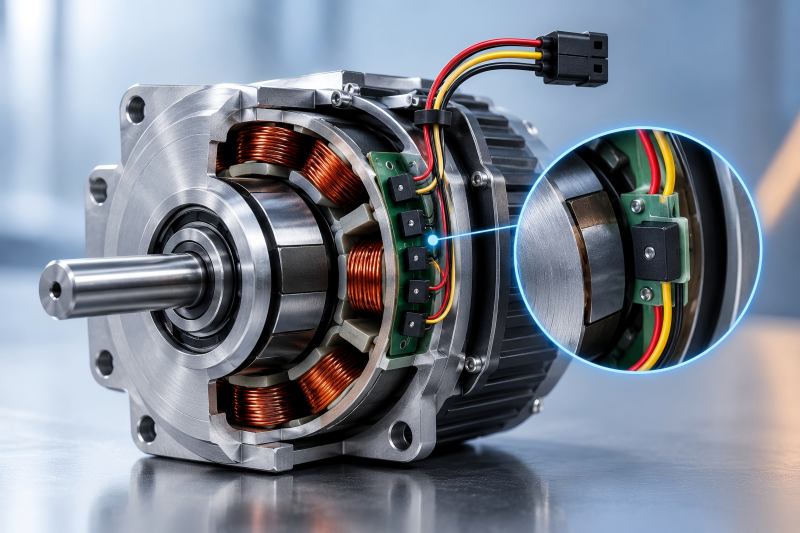
1. Hall Sensor Control
Hall sensors are one of the most common rotor-position feedback methods used in BLDC motors.
A three-phase BLDC motor typically uses three Hall sensors for rotor detection. As the rotor magnets move past them, the Hall signals change state and provide the controller with information about the rotor’s electrical position.
For conventional six-step commutation, this is often enough.
Where Hall Sensors Perform Well
The biggest practical advantage of Hall sensors is that they work at zero and very low speed.
The controller does not need the rotor to already be rotating before receiving position information. This makes startup relatively straightforward, especially when the motor must start under load.
Hall sensors balance reliable performance with affordable system costs. They are inexpensive compared with high-resolution encoders and do not require sophisticated position-estimation algorithms. They are widely used in applications including:
- pumps
- fans and blowers
- power tools
- small electric vehicles
- actuators
- conveyors
- household appliances
- general industrial drives
For these applications, knowing the approximate commutation sector may be more important than knowing the exact shaft angle.
Limitations of Hall Sensors
Hall sensors provide relatively coarse position information.
In a typical six-step BLDC system, Hall states mainly tell the controller which commutation sector the rotor occupies. They do not provide the fine angular resolution expected from a servo feedback device.
This can become noticeable when the application requires extremely smooth low-speed rotation or accurate position control.
Hall systems also introduce physical components into the motor. Sensors must be correctly positioned, connected, and protected against temperature, vibration, moisture, contamination, and electrical interference.
Their alignment matters as well. A poorly positioned Hall sensor can shift the commutation timing and reduce motor performance even if the motor itself is mechanically correct.
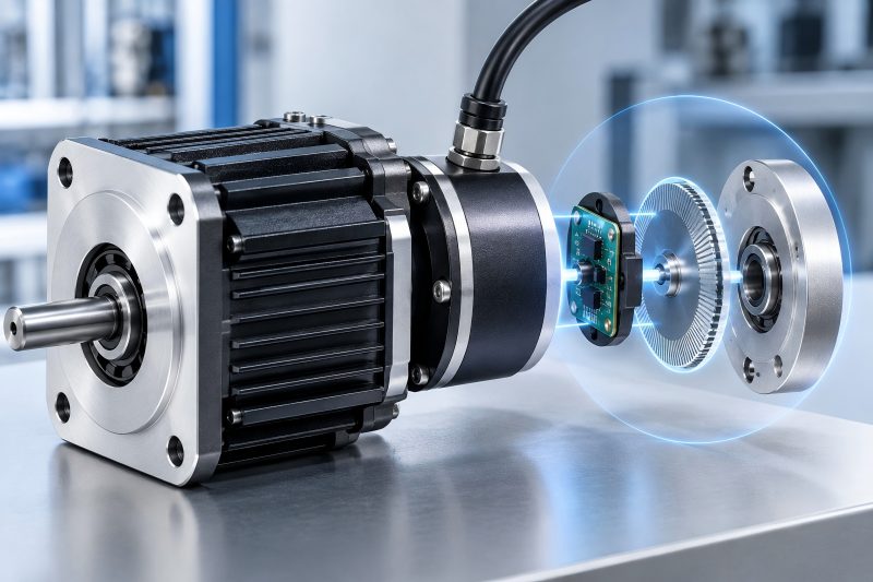
2. Encoder Control
An encoder provides much more detailed information about shaft or rotor movement.
Depending on the design, an encoder can provide position, speed, direction, and sometimes absolute shaft angle. Common options include incremental optical encoders, magnetic encoders, and absolute encoders.
For applications where the motor is part of a motion-control system rather than simply a rotating power source, this additional information can be extremely valuable.
Why Encoders Offer Better Motion Control
Consider a robotic joint.
Knowing that the rotor is somewhere inside a 60-degree electrical commutation sector is not enough. The controller may need to know exactly how far the joint has moved, whether it has reached the commanded position, and how quickly it is approaching the target.
An encoder makes this possible.
Higher-resolution position feedback can support:
- precise speed regulation
- accurate positioning
- smooth low-speed motion
- servo control
- closed-loop torque control
- rapid acceleration and deceleration
- better disturbance correction
This is why encoders are commonly found in robotics, CNC machinery, automation equipment, servo drives, precision actuators, and other motion-control systems.
Encoder Resolution Is Not Automatically Better
One mistake in motor-system design is assuming that more encoder resolution always produces a better machine.
It does not.
A high-resolution encoder only becomes useful when the mechanical system, controller, bearings, gearbox, motor construction, and control loop can take advantage of that information.
If a gearbox has significant backlash, for example, extremely fine motor-side encoder resolution cannot eliminate the mechanical lost motion at the output.
Likewise, adding an expensive encoder to a ventilation fan would usually provide information that the application never uses.
Feedback resolution should therefore be selected at system level rather than treated as an isolated specification.
Encoder Trade-Offs
The main disadvantages are cost and complexity.
An encoder may require additional mounting space, wiring, connectors, signal processing, calibration, and controller inputs. The mechanical installation also becomes more important because misalignment or contamination can affect some encoder technologies.
In harsh environments, the feedback device must be selected carefully.
Magnetic encoders may be attractive where dust, oil, or vibration makes optical sensing difficult. Optical encoders, meanwhile, can provide excellent resolution where environmental conditions are controlled.
The best encoder is therefore not simply the one with the highest resolution. It is the one whose accuracy, environmental resistance, interface, speed capability, and cost match the machine.
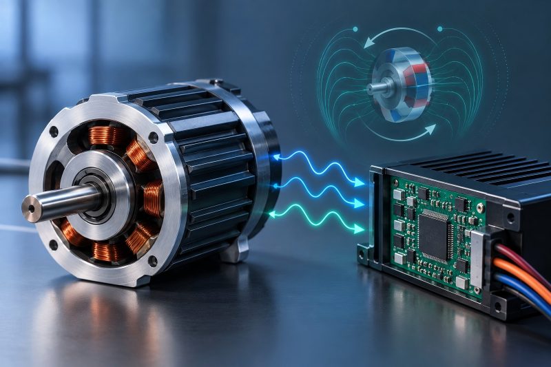
3. Sensorless BLDC Control
Sensorless control removes the dedicated rotor-position sensor and estimates rotor position from electrical behavior inside the motor.
One common approach detects back electromotive force, or back-EMF. Other control methods may estimate rotor position using motor current, voltage, flux models, observers, or more advanced estimation algorithms.
The main attraction is obvious: fewer physical components.
There are no Hall sensors or encoders inside or attached to the motor for rotor feedback.
This can reduce:
- sensor cost
- connectors
- wiring
- assembly steps
- potential sensor failures
- motor packaging complexity
For high-volume applications, removing even a small number of components can have a meaningful effect on total system cost.
The Main Sensorless Challenge: Low Speed
Back-EMF depends on motor rotation.
When the rotor is stationary, there is essentially no useful back-EMF available for conventional detection. At very low speeds, the signal is also weak and can be difficult to separate from switching noise and other electrical effects.
This creates the fundamental challenge of traditional sensorless BLDC control: the controller needs rotor-position information to control the motor, but some of the information used to estimate position only becomes useful after the motor begins rotating.
Startup therefore often requires a different strategy.
The controller may first align the rotor, apply an open-loop commutation sequence, accelerate the motor to a usable speed, and then transition into closed-loop sensorless operation.
That works very well in many applications. It is less attractive when the motor must produce tightly controlled torque immediately from standstill.
Where Sensorless Control Makes Sense
Sensorless control is particularly suitable when the motor normally operates above a minimum speed and precise zero-speed positioning is unnecessary.
Typical examples include:
- cooling fans
- blowers
- compressors
- centrifugal pumps
- high-speed spindles
- certain household appliances
- some power tools
A fan is a good example.
Once the rotor accelerates, electrical position estimation can work reliably, while removing physical sensors simplifies the motor assembly. The application generally does not care about the exact shaft position when the fan is stopped.
A robotic joint is very different.
The joint may need to hold a known position at zero speed, move slowly with controlled torque, reverse immediately, and maintain accurate angular information. Encoder feedback is usually much more appropriate.
Hall Sensors vs Encoders vs Sensorless Control
| Factor | Hall Sensors | Encoders | Sensorless |
| Rotor feedback | Direct | Direct | Estimated |
| Zero-speed position detection | Good | Excellent | Limited with conventional methods |
| Low-speed control | Good | Excellent | More challenging |
| Position resolution | Low | High to very high | Depends on estimation method |
| Position control | Limited | Excellent | Generally limited |
| Startup under load | Good | Excellent | Application-dependent |
| Hardware cost | Low–medium | Medium–high | Low |
| Wiring complexity | Moderate | Higher | Low |
| Control algorithm complexity | Low–medium | Medium | Medium–high |
| Sensor failure risk | Present | Present | Eliminated |
| High-speed continuous rotation | Good | Good | Excellent fit |
| Servo applications | Limited | Excellent | Usually not first choice |
The table highlights an important point: removing a sensor does not remove the need for rotor-position information. It changes where that information comes from.
With Hall sensors or encoders, position is measured physically. With sensorless control, the controller has to reconstruct it from electrical signals and a model of motor behavior.
Sensorless hardware may therefore be simpler while the software becomes more sophisticated.
Startup Behavior Often Decides the Choice
When comparing these technologies, startup deserves more attention than it usually receives.
Suppose a motor drives a pump that normally starts with very little load. A short open-loop startup period may be completely acceptable. Sensorless control can be a practical solution.
Now consider a motor driving a loaded conveyor.
The controller may need reliable rotor-position information before meaningful movement begins. Hall feedback gives the controller immediate commutation information and can make loaded startup more predictable.
For a precision positioning axis, the requirement goes further. The controller may need not only commutation information but accurate mechanical position. An encoder becomes the natural choice.
This gives a useful selection sequence:
Does the motor need controlled torque from standstill?
If no, sensorless control deserves serious consideration.
If yes, determine whether basic commutation information is sufficient.
If it is, Hall sensors may be enough.
If accurate shaft position and motion feedback are also required, an encoder is usually the better solution.
Think About the Complete Drive System
The feedback method should never be selected from the motor specification alone.
The controller matters just as much.
A motor equipped with a high-resolution encoder will not automatically deliver excellent servo performance if the drive electronics, current sensing, control-loop bandwidth, tuning, and mechanical transmission are poorly designed.
Similarly, sensorless control depends strongly on the controller’s estimation method and the electrical characteristics of the motor.
Motor parameters such as resistance, inductance, back-EMF characteristics, pole count, operating speed range, and load behavior can influence how easily a sensorless algorithm can estimate rotor position.
The motor and controller should therefore be treated as one drive system.
Reliability Is More Complicated Than Sensor Count
It is tempting to say that sensorless systems are always more reliable because they contain fewer sensors.
Sometimes they are.
Removing Hall devices, encoder assemblies, connectors, and feedback wiring eliminates several potential hardware failure points. This can be particularly valuable in motors exposed to vibration, heat, moisture, or difficult maintenance conditions.
But reliability also means predictable operation across the full operating envelope.
A sensorless motor that struggles to restart under a particular load condition is not more reliable simply because it has fewer components.
The correct comparison should include:
hardware reliability + startup reliability + control stability + environmental conditions + maintenance requirements.
Choosing the Right Feedback Method
The most practical selection criteria are straightforward.
Choose Hall sensors when the motor needs reliable startup and low-speed commutation, but precise shaft positioning is unnecessary. They offer a strong balance between cost, simplicity, and usable performance.
Use an encoder for precise speed, position, and motion control. The additional cost is justified when precision directly affects machine performance.
Choose sensorless control when the motor spends most of its operating time at moderate or high speed, exact zero-speed position is unnecessary, and reducing hardware, wiring, size, or manufacturing cost provides a real advantage.
For many products, the decision can be summarized as:
Hall sensors = practical commutation feedback
Encoders = precision motion feedback
Sensorless = simplified hardware with position estimated electronically