
A gear motor noise limit is meaningful only when the supplier and customer measure the same operating condition in a comparable setup. Mounting stiffness, load, microphone position and background sound can change the reported result. Define those conditions before using a decibel value to accept or reject a shipment.
This is different from a quick listening check for scraping or unusual vibration. Such a check can identify an obvious problem, but it cannot by itself explain why two laboratories report different numbers for the same unit.
What Acoustic Quantity Is Being Specified?
Start by naming the quantity and reporting convention. Sound pressure measured at a particular location is not the same as sound power emitted by the source. Weighting, averaging period and frequency information also influence what a reported number means.
A specification stating only a maximum dB value leaves too many questions unanswered. Identify the measurement quantity, any frequency weighting, the operating interval and the method used. If a formal standard is required, name its applicable edition and confirm that the setup follows it.
For a micro planetary gear motor, the acoustic result may reflect the motor, gear train, bearings and mounting structure together. Decide whether acceptance concerns the purchased assembly alone or its behavior in the customer’s product. Those are related but different test boundaries.
The FHWA noise measurement handbook discusses measurement planning, instrumentation and background noise in a transportation context. Its general measurement considerations help explain why conditions matter, but it does not establish a gear motor acceptance limit or replace a relevant motor test method.
How Can Mounting Change the Result?
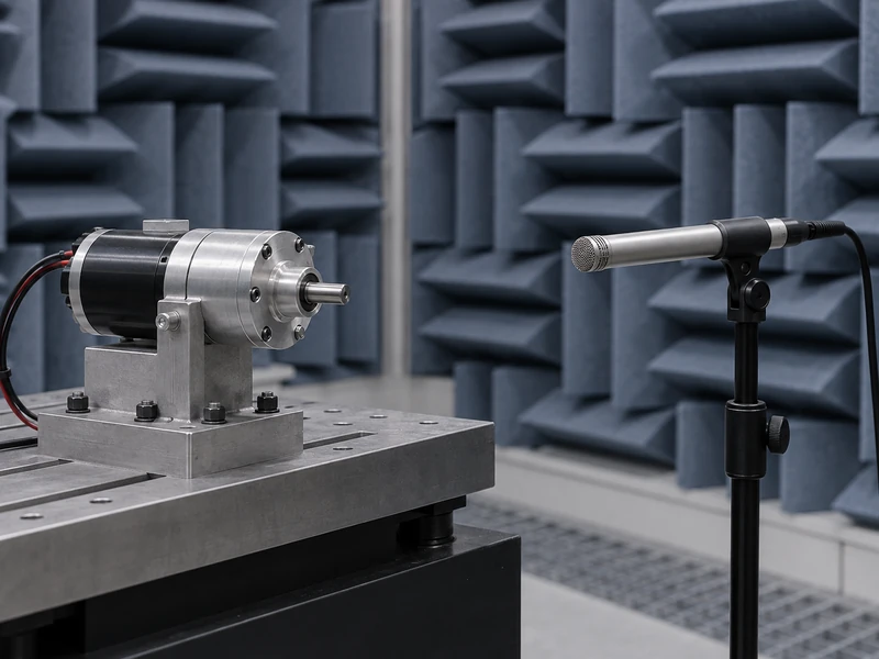
A thin panel can radiate sound differently from a rigid laboratory block. Fastener torque, contact area, mounting orientation and the presence of a coupling can all change the assembly’s response. A supplier’s fixture should therefore be described well enough for the customer to reproduce its important features.
Do not treat a soft foam support as automatically more representative or more accurate. It may reduce one transmission path while creating a condition unlike the installed product. The appropriate fixture follows the purpose of the test.
Specify the mounting interface and any attached output components. A long unsupported coupling, a resonant bracket or a misaligned load can add noise that is not intrinsic to the gear motor. Conversely, an unusually massive fixture may suppress behavior that matters in the real enclosure.
Gian’s guide to gear motor dimensions and specifications provides useful mechanical context. Include those interface details in the acoustic procedure rather than assuming that identical motor part numbers guarantee identical mounting conditions.
Which Operating Points Should Be Compared?
Define input voltage or control mode, output speed, torque, direction and the duration of operation before measurement. A no-load result cannot automatically represent loaded service. Gear contact and motor current can change with the applied load.
Use the same warm-up procedure for comparison tests. Lubrication and temperature may influence the acoustic response, so one laboratory measuring immediately after startup and another measuring after prolonged running can obtain different results. Record temperature where it is relevant to the agreed method.
Include the operating points important to the end product. A mechanism that reverses frequently may need separate observations during steady motion, reversal and stopping. Averaging the entire sequence can hide a short event that users find objectionable.
Keep electrical control settings fixed. PWM frequency, current regulation and commutation behavior can contribute audible components. When comparing a brushless DC motor assembly, identify the driver configuration as part of the acoustic setup.
Where Should the Microphone Be Placed?
Define the microphone location relative to a repeatable datum on the assembly or fixture. Specify distance, height, orientation and the number of measurement positions. A photograph is helpful, but a dimensioned layout prevents perspective from becoming the only location reference.
Nearby reflecting surfaces and other equipment should be considered. A desk, wall or large enclosure can affect the sound field at the microphone. Moving the same fixture to a different room corner may change the result even when the motor behavior remains unchanged.
Measure and document background conditions under the agreed procedure. If unrelated sound is too close to the motor’s measured level, the result may not distinguish the source adequately. Apply only the background treatment permitted by the chosen method; do not improvise a subtraction directly on decibel values.
Keep microphone cables and supports from contacting vibrating parts unintentionally. Record instrument settings, calibration checks and any windscreen used. These details help another laboratory reproduce the measurement and investigate discrepancies.
What Belongs in a Shared Acceptance Procedure?
The procedure should be specific enough to reproduce and short enough to use routinely. Separate the essential controlled conditions from descriptive observations. If a condition is allowed to vary, state its permitted range and how that variation is handled.
| Procedure Element | Required Definition |
| Assembly and fixture | Part revision, mounting interface and attached components |
| Operating condition | Speed, load, direction, supply and driver settings |
| Acoustic measurement | Quantity, weighting, microphone position and averaging interval |
| Environment | Room arrangement and acceptable background conditions |
| Decision rule | Limit, uncertainty treatment and handling of borderline results |
Agree on the decision rule before testing a disputed batch. A result close to the limit should be interpreted with the measurement capability and agreed acceptance rule in mind. Repeating measurements until one falls below the limit is not a defensible release method.
Define sampling separately from the acoustic setup. The number of units tested and their selection determine what the result says about a shipment. A carefully measured prototype does not automatically establish the distribution of production units.
How Should Supplier and Customer Results Be Correlated?
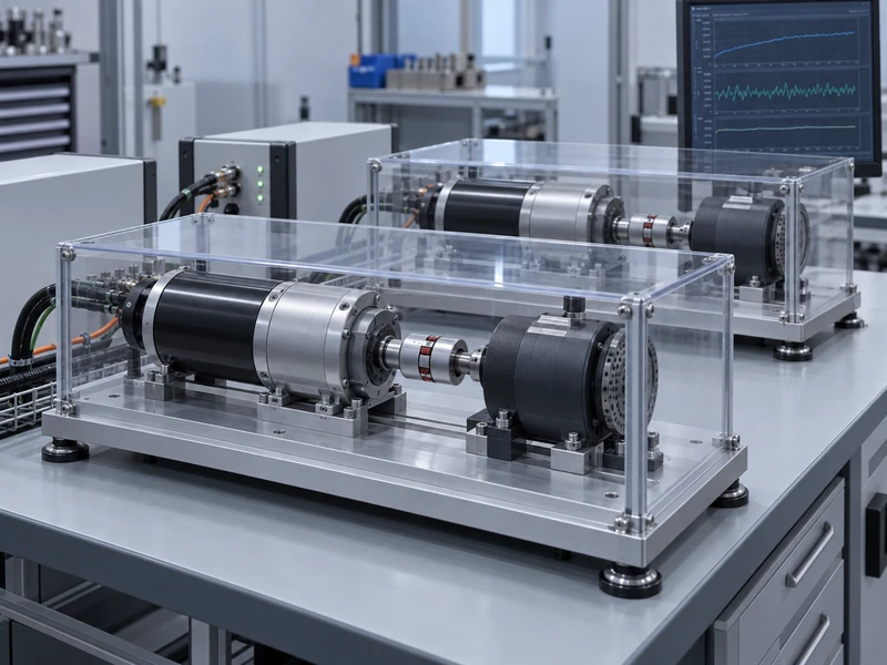
Use the same identified samples in both locations where practical. Retain their condition and test history, because handling, running time or damage between tests can complicate the comparison. A small set of comparison units is more informative than unrelated samples with unknown variation.
Begin by matching the written method and reviewing the fixtures. Then compare measurement results, including frequency information when it helps identify a difference. A similar overall level can conceal different tonal components, while a small overall difference may come from background sound.
If the disagreement remains, change one setup factor at a time. Moving the microphone, changing the fixture and altering the load together may produce agreement without showing why. Preserve the original results so the investigation remains traceable.
Gian’s pre-installation gear motor test guide covers broader functional inspection. Use it alongside the acoustic protocol, while keeping the quantified noise acceptance method distinct from a general listening check.
What Does an Unexpected Noise Result Mean?
An unexpected level is a reason to investigate, not an immediate diagnosis of a particular failed component. Check the setup, load alignment, electrical control and sample identity before attributing the result to the gearbox. Compare with a known acceptable unit under the same conditions.
Frequency patterns and changes with speed can help guide the investigation, but they should be interpreted by someone familiar with the assembly. Avoid assigning a specific defect from one overall sound-pressure number. Supporting mechanical and electrical evidence may be needed.
Gian’s article on common gearbox failures provides background for a subsequent mechanical review. The acoustic record should preserve what was measured without turning an unverified explanation into the reported result.
What Should Be Sent With a Noise Requirement?
Send Gian the product’s important operating points, mounting drawing, proposed acoustic method and acceptance rule. Include whether the requirement concerns steady sound, a particular transient or a tonal characteristic. If a reference sample exists, identify it and explain how it was accepted.
Keep the resulting procedure with the approved assembly revision. Changes to the gear train, motor, driver, fixture or enclosure may require a targeted comparison. A useful noise specification allows both sides to reproduce the result and understand exactly which product behavior it controls.