
A D-flat shaft can work for a reversing BLDC drive when its hub fit and retention withstand bidirectional torque. A keyed interface transfers torque through key flanks, but clearance can introduce lost motion.
OEM engineers should measure positive and negative torque, shaft-to-hub angular play, and retention after cyclic loading before selecting the production interface.
How Do D-Flat and Keyed Shafts Behave Under Reversing Torque?
D-Flat Shaft Torque Transmission
A D-flat removes part of the shaft circumference to create a defined driving surface. Whether that surface carries torque depends on the mating hub, not the shaft drawing alone.
With a complementary D-shaped opening, the hub bears against the shaft profile to resist rotation. Put that same shaft inside a circular bore and the load path changes: screw seating and the assembled frictional restraint now determine how the hub stays in place.
- Contact geometry: Inspect the effective flat length and whether the hub bears across the intended surface rather than on an edge.
- Fastening: Specify screw location or clamp arrangement and the assembly procedure needed to reproduce the joint.
- Movement: Check both directions because clearance can permit a small rotation before the opposite surface engages.
Keyed Shaft Torque Transmission
A parallel key links shaft and hub through their keyways. Under torque reversal, load can shift from one key flank to the other, depending on the clearances and assembly.
The key provides positive engagement, but that does not make the joint rigid or automatically free of play. Key width, engagement length, and the fit of both keyways matter.
- Flank bearing: Assess contact pressure across the loaded key and keyway surfaces.
- Local strength: Assess key shear and shaft fatigue near the keyway, especially at geometric transitions.
Why Torque Reversal Changes the Design Problem
Reversing rotational direction is not always the same as reversing transmitted torque. Define the torque sign at the shaft-hub joint and capture it during representative operation.
As torque changes sign, unloaded gaps close and contact shifts. This can cause impact, angular lost motion, or microscopic sliding that gradually produces fretting and looseness.
An encoder may report precise motor rotation while a loose hub responds later. For position-controlled machinery, specify allowable relative angle at the actual driven member.
Also check whether deceleration creates a higher joint load than steady running. Controller settings and reflected load inertia can change which operating event governs selection.
D-Flat vs. Keyed Shaft: Which Better Fits the Load?
Neither profile has a universal torque limit. Shaft diameter, hub material, engagement length, applied loads, manufacturing tolerance, and fastening method determine whether a particular connection is suitable.
| Selection Factor | D-Flat Interface | Keyed Interface |
| Torque path | Matching-profile contact, set-screw restraint, or clamping, according to hub design | Mechanical bearing between key and keyway flanks |
| Reversal backlash | Driven by bore fit, contact geometry, and retention | Driven primarily by lateral key and keyway clearance |
| Wear concern | Local slip, set-screw marks, or fretting | Flank fretting, peening, or keyway wear |
| Strength concern | Local stresses at the flat and joint contact | Key shear, flank pressure, and shaft keyway fatigue |
| Assembly concern | Hub alignment and reliable clamping or screw seating | Key fit, insertion, and separate axial retention |
When a D-Flat Is a Reasonable Choice
A D-flat may suit a compact reversing drive if the selected hub maintains contact and retention through the full load cycle. Compactness alone does not establish suitability.
Consider an illustrative actuator with frequent direction changes but modest interface loads. The deciding evidence would be measured slip and backlash after cycling, not its nominal motor power.
- Prefer the option: When packaging favors it and qualification confirms stable engagement in both torque directions.
- Reconsider the option: When screw loosening, permanent movement, or concentrated contact damage appears during testing.
When a Keyed Interface Is Worth Considering
A keyed interface provides a defined path for transmitting torque without relying exclusively on friction. That can be useful when a design needs positive engagement at the shaft-hub connection.
However, the key must fit both slots, and its contact surfaces must withstand alternating load. A keyway also removes material from the shaft and changes local fatigue behavior.
Illustrative example: a reversing indexing mechanism might favor positive key engagement yet reject the resulting lost motion. A tighter fit or different hub concept would then need evaluation.
The same mechanism could accept a well-clamped D-flat if testing demonstrates no consequential slip. The operating requirement, rather than an interface label, decides the tradeoff.
- Prefer the option: When the available shaft and hub dimensions permit an adequately sized, validated key connection.
- Reconsider the option: When keyway clearance causes unacceptable lost motion or the remaining shaft section lacks fatigue margin.
Choose by Failure Mode, Not Profile Reputation
List the most damaging credible failure for each candidate: slipping, loosened screws, flank wear, excessive backlash, or shaft cracking. Then test the conditions likely to provoke it.
For custom brushless DC motor integration, treat the interface as a model-specific mechanical decision alongside the electrical requirements, not as a feature guaranteed by motor category.
Which Shaft and Hub Dimensions Control Fit and Backlash?
Measure the D-Flat and Its Mating Bore
Start with shaft diameter, flat depth, effective flat length, and the position of the flat relative to shoulders. Inspect the mating bore rather than assuming nominal dimensions match.
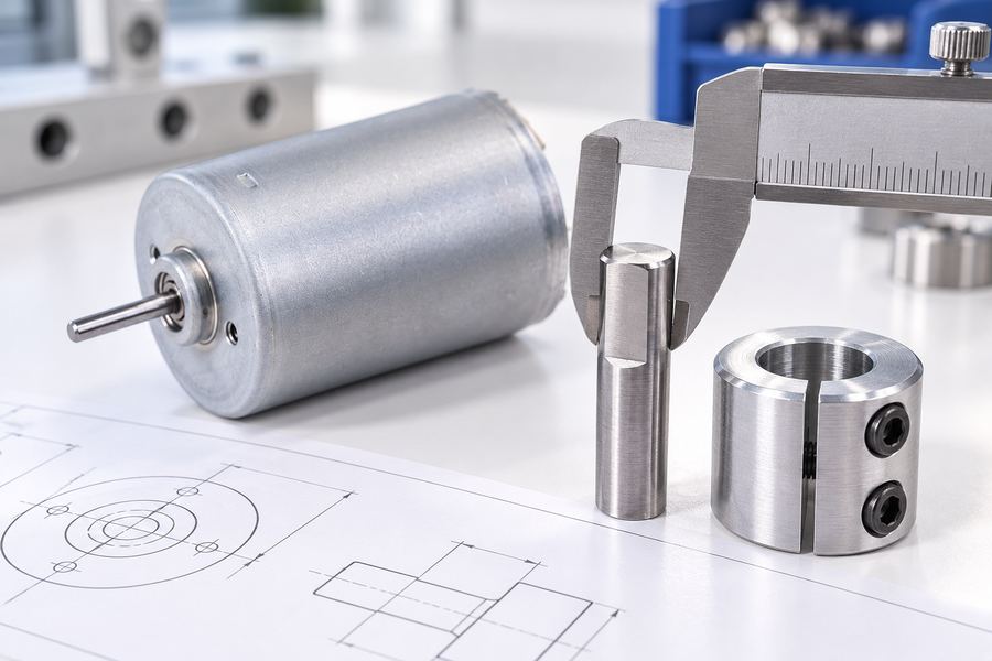
Illustrative d flat shaft fit inspection arrangement.
A matching D-bore needs appropriate profile tolerance; a round-bore set-screw arrangement requires verified screw contact. In either case, bore clearance and engagement length affect actual movement.
- Drawing control: State how the flat depth and geometry will be dimensioned and inspected.
- Contact control: Check whether assembly leaves full intended engagement without edge loading or bottoming on a shoulder.
Measure Key and Keyway Fit
Record shaft diameter, key width and height, effective engagement length, and both keyway widths and depths. A nominally matching key can still have excessive flank clearance.
The relevant clearance is circumferential movement between opposed contact surfaces, not simply whether the key slides into place. Check keyway root geometry for strength assessment.
- Fit check: Examine the assembled key, not just each component in isolation.
- Strength check: Evaluate local keyway stresses and any nearby shoulders or diameter changes.
Measure Angular Lost Motion Directly
Lock the driven hub or shaft in a suitable fixture, apply controlled torque in each direction, and measure relative angular position across the joint. Capture applied torque simultaneously.
Subtract neither gearbox backlash nor shaft twist by guesswork. Instrument the shaft and hub independently, or characterize fixture compliance to separate elastic deflection from actual clearance.
As an illustrative geometry calculation, 0.3 degrees of relative rotation equals about 0.052 mm of arc travel at a 10 mm radius: s = r × angle in radians. This is not an allowable tolerance.
Record angular displacement at defined torque points and report the complete loading path. A single peak-to-peak number hides whether movement came from clearance, compliance, or irreversible slip.
Repeat after disassembling and reassembling representative samples. A joint that performs well only after one careful adjustment may be difficult to manufacture consistently.
How Can Fastener Retention and Interface Wear Be Controlled?
Control D-Flat Fastening
A set screw may create local contact pressure, but installation torque is not the same as transmitted torque capacity. The result also depends on thread condition and joint geometry.
Specify screw type, seating location, tightening method, and any validated anti-loosening provision. For a split-clamp hub, evaluate clamping force and friction under both torque directions.
- Verification: Mark shaft and hub positions to detect rotation during testing, then confirm with measurements.
- Retention: Inspect screw condition and clamp integrity after cyclic operation, without disturbing evidence before inspection.
Retain a Keyed Hub Axially
A conventional parallel key is primarily intended to transmit torque. It should not be assumed to stop the hub moving along the shaft during acceleration or vibration.
Use an axial-retention arrangement appropriate to the assembly, such as a shoulder and retainer, and confirm that movement cannot reduce key engagement or compromise nearby components.
Check the direction and magnitude of axial forces as well as assembly access. Retention hardware that interferes with a bearing, seal, or service operation can create a separate failure.
Do not assume a tight key fit supplies controlled axial friction. Record axial position before and after testing independently of the torque-transfer inspection.
Recognize Fretting Before Looseness Grows
Alternating micro-slip can leave dark debris, polished tracks, or localized wear on either interface. Inspect both mating surfaces, because a clean exterior may conceal internal damage.
Compare the post-test angular play with the initial measurement. Increasing lost motion is often more informative than the presence of cosmetic marks alone.
Surface finishes and lubricants may alter wear behavior, but neither fixes a fundamentally loose interface. Assess any treatment with the same materials, loads, and assembly procedure planned for production.
If wear is concentrated at one edge, investigate hub misalignment or partial engagement before merely increasing fastener torque. The underlying contact pattern may remain unchanged.
How Should OEM Engineers Qualify a Reversing-Load Interface?
Capture Real Operating Torque
Define the sign convention first, then record transmitted torque during starts, stops, reversals, and abnormal but credible events. Capture torque peaks, dwell time, and cycle frequency.
Motor current alone is an indirect estimate unless the motor and controller behavior are characterized. Where possible, measure joint torque directly or validate the estimation method.
- Duty cycle: Record how frequently torque changes sign and the time spent at representative load levels.
- Boundary conditions: Include driven inertia, control behavior, temperature, vibration, and any expected shock loading.
Separate Slip, Backlash, and Elastic Twist
Apply a controlled torque sweep through zero into both directions while measuring relative shaft-hub angle. Repeat several times to identify stable play and progressive changes.
Elastic deflection changes with torque and recovers on unloading. Clearance-driven lost motion appears when contact transfers; permanent slip leaves a residual offset after torque returns.
Check measurement resolution and fixture stiffness before treating a tiny observed displacement as interface backlash. Reverse the test sequence where useful to expose setup hysteresis.
Place angular sensors as close as practical to the two joined components. Measuring only motor encoder angle against a remote output mixes joint clearance with other drivetrain effects.
For small movements, repeat measurements at the same temperature and fixture orientation. Thermal expansion and mechanical seating can otherwise look like changes in fit.
Run Reversal and Durability Tests
Choose torque amplitude, reversal waveform, cycle count, and environmental conditions from the intended application. A test at constant speed without actual torque reversal may miss the governing failure.
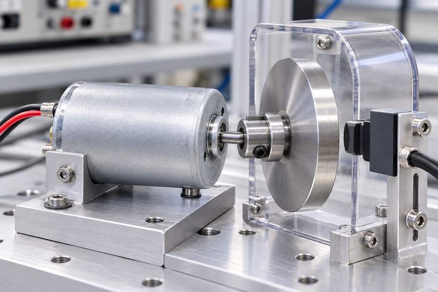
Illustrative keyed shaft reversal test arrangement.
Measure backlash before and after cycling, and inspect the connection for screw movement, fretting, hub contact damage, axial migration, cracked material, or a deformed key.
Do not dismantle the joint before documenting alignment marks and axial position. Disassembly can erase evidence of the contact state that produced a failure.
Where the design permits, test more than one assembly and include reasonable manufacturing extremes. This helps distinguish a robust interface from an unusually favorable specimen.
An illustrative test sequence might include initial fit inspection, bidirectional torque sweeps, reversal cycling, another sweep, and controlled teardown. Actual loads and cycle counts remain project-specific.
Set Acceptance Criteria Before Testing
There is no defensible universal backlash angle or reversing-torque threshold for both shaft profiles. Acceptance limits must come from system function, safety margin, and durability requirements.
| Check | Measurement | Acceptance Basis |
| Torque transfer | Positive and negative applied torque | Verified operating load envelope |
| Backlash | Relative angular play, in degrees or radians | Allowable system positioning error |
| Permanent slip | Residual shaft-hub angle after unloading | Project-specific movement limit |
| Retention | Fastener condition and axial displacement | Approved assembly requirements |
| Wear and integrity | Flank, flat, hub, and shaft inspection | Defined damage and fatigue criteria |
State the test fixture, measurement accuracy, temperature range, and pass/fail definitions in the report. Otherwise, two apparently similar trials may not be comparable.
What Must Be Verified Before Production Approval?
Confirm Repeatable Dimensions
Inspect finished shaft geometry and representative mating hubs against the approved drawings. Pay attention to flat depth, keyway width, engagement length, and transitions that influence fatigue.
Dimensional compliance alone is insufficient if assembly changes the contact pattern. Check assembled fit, runout where relevant, and the position of any axial retaining features.
Specify measurement datums on the drawing. Without common datums, a shaft flat and mating hub bore may individually pass inspection yet assemble with unwanted eccentricity.
Use gauges or calibrated instruments suited to the critical tolerances. A visual inspection cannot establish small keyway clearances or confirm the repeatability of a machined flat.
Make the Assembly Method Reproducible
A validated prototype can fail in production when its screws are tightened differently or a key is substituted. Record tooling, torque procedure, sequence, and component identification.
- D-flat assembly: Verify hub orientation, screw seating, and the specified clamping or tightening procedure.
- Keyed assembly: Verify key fit, full engagement, hub seating, and separate axial retention.
- Inspection: Check that assembly records connect each sample to its measured geometry and test condition.
Link Prototype Results to Lot Inspection
Use prototype qualification to identify which dimensions and assembly variables predict joint behavior. Those become candidates for production checks, with sampling based on application risk.
Do not convert one passing prototype into a broad performance guarantee. Control design revisions, tooling changes, and alternative hub components so their impact can be reassessed.
What Should an OEM Send to Gian Transmission for a Custom Shaft Review?
Supply a Matched Shaft-and-Hub Drawing Set
Provide the shaft drawing together with the actual hub profile and fastening arrangement. A shaft specification by itself cannot establish backlash, contact conditions, or retention.
Include shaft diameter, flat or keyway dimensions, effective engagement, shoulders, material assumptions, and dimensional tolerances. Identify which dimensions are critical to assembly function.
When considering an inrunner brushless DC motor, confirm the available shaft envelope and mechanical interface for the specific proposed model; category descriptions do not certify a shaft configuration.
Define Loads and Acceptance Targets
Provide peak positive and negative torque, reversal frequency, rotational speed range, acceleration, driven inertia, and expected service conditions. Explain how the values were measured or calculated.
Include the motor control mode and any torque-limiting behavior used to establish the duty cycle. Changing control settings may change the loads seen by the same shaft connection.
Separate normal running from foreseeable jams or emergency stops, and state whether those events require continued operation, inspection, or replacement afterward.
Set permissible backlash, permanent slip, axial movement, and post-cycling wear criteria according to the system. Keep any assumed duty-cycle values clearly separated from measured operating data.
Hand Over a Testable, Controlled Specification
Agree on drawing revision, inspection method, fastening instructions, test profile, sample traceability, and explicit pass/fail limits. Include who measures the assembled connection and how results are recorded.
For a Gian Transmission review, submit the evidence and drawings through the technical contact page. The final handover should identify the selected interface, mating hub, approved tolerances, and qualification record required before release.