
Prioritize tolerances that establish gear alignment, tooth clearance, planet-pin position, bearing support, and output reference accuracy. A custom planetary gearbox needs those relationships controlled as an assembly; making every individual dimension tighter is not an efficient substitute. Start with the load path and inspection datums, then assign limits to the characteristics that govern performance.
This approach is particularly important when a compact CAD model is being prepared for its first machined build. The model can show that the nominal parts fit while saying little about how manufacturing variation will affect contact. The production drawing must describe the acceptable variation and how it will be measured.
Why Is Nominal Geometry Not Enough?
Nominal geometry represents one ideal arrangement. Real parts contain dimensional and geometric variation, and the assembly combines those variations. A reducer may turn differently depending on which parts are paired and how the housing is tightened.
Begin by defining the output requirement. Acceptable backlash, loaded deflection, running drag, noise, temperature, and life are different outcomes, even though some share the same geometric causes. A tolerance should support one or more identified outcomes rather than simply make a drawing look precise.
Before designing every component from scratch, compare the requirement with a documented planetary gear motor platform. An existing platform can reduce development effort when its interfaces and performance fit. A custom design remains justified when the application has constraints that the available platform cannot meet.
Which Datums Should Anchor the Design?
Use datums that represent how the reducer is located and supported in service. Typically, the relationships between bearing seats, mounting faces, and the output axis deserve early attention. The appropriate datum scheme depends on the actual architecture and assembly sequence.
Ask whether the inspection setup reproduces those functional references. A part can meet measurements taken from an arbitrary surface while failing to align correctly in the housing. Clear datums help the manufacturer and inspector evaluate the same intended geometry.
Avoid creating an unnecessarily long chain of dependent dimensions. Where possible, control critical relationships directly from the functional references. Review the drawing with the intended manufacturing and inspection processes before declaring a tolerance achievable.
Why Do Planet-Pin Locations Matter So Much?
The carrier locates multiple planets relative to the sun and ring. Errors in pin position, orientation, or support can change the engagement conditions around the stage. The result may be unequal contact, increased drag, or an output response that varies with position.
Do not assume that adding more planets automatically divides the load equally. Actual sharing depends on geometry, stiffness, clearances, and the design’s ability to accommodate variation. The manufacturing plan must support the load-sharing assumptions used in the design analysis.
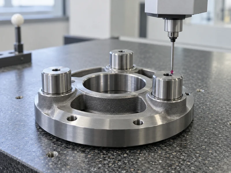
Inspect the carrier as a functional component. Pin bores or seats need relationships to the carrier’s rotational reference, and the assembled pins need suitable support and retention. A precise hole diameter does not establish accurate location or perpendicularity.
GIAN’s overview of planetary gearbox backlash causes identifies carrier and assembly influences. Use those categories to organize an inspection plan, then set limits from the specific design rather than copying generic values.
How Should Tooth Thickness and Backlash Be Specified?
Specify the gear geometry and its permitted variation through an appropriate drawing and measurement method. Tooth thickness, center distance, and tooth deviations influence the clearance at the mesh. A blanket request for zero backlash does not tell the manufacturer which dimensions to produce or the inspector what to accept.
The public scope of ANSI/AGMA 2002-D19 describes procedures linking tooth thickness measurements and backlash calculations for cylindrical involute gearing. That scope is a useful reference for selecting the relevant method; it is not a substitute for applying the complete standard and design analysis.
Define how backlash is checked on the finished assembly. State the input restraint, output measurement method, applied test torque, angular positions, and temperature conditions. Without this definition, two suppliers can report different values for the same general term.
Where a preloaded design is considered, evaluate its effect on friction, temperature, wear, and manufacturing sensitivity. Removing perceptible play during a hand test is not sufficient evidence that the preload is suitable for the operating cycle. The assembled reducer needs loaded and thermal validation.
Which Bearing and Housing Relationships Are Critical?
Bearing seats determine how the shafts are supported and aligned. Their size, form, relative position, shoulders, and retention features can all influence the final assembly. The correct limits depend on bearing type, loading, material, temperature, and the assembly method.
Housing distortion also deserves attention. A bearing bore measured before assembly may change when a cover is tightened or the reducer is mounted to a nonflat surface. Identify whether any critical inspection needs to occur in an assembled or restrained condition.
| Characteristic | Function Protected | Possible Assembled Symptom |
| Carrier pin position | Gear engagement and load sharing | Uneven running behavior |
| Bearing-seat alignment | Shaft support and mesh alignment | Drag, heat, or vibration |
| Gear reference runout | Consistent mesh geometry | Position-dependent clearance |
| Mounting-face geometry | Installed alignment and support | Performance changes after mounting |
These symptoms guide investigation but are not unique diagnoses. High drag can have several causes, including lubrication or seal behavior. Use measurements to isolate the source before changing a tolerance.
How Can Tolerances Be Allocated Without Overspending?
Work backward from the allowable assembled variation and identify the contributors. A tolerance stack or sensitivity analysis helps show which dimensions strongly influence the result. Spend manufacturing effort on those contributors rather than assigning the same tight limit throughout the drawing.
Consult the supplier about process capability and inspection access. Before freezing a modeled feature, confirm access for finishing and inspection and allow for the dimensional effects of heat treatment. A modest geometry change can sometimes make a critical relationship easier to manufacture reliably.
Separate prototype assumptions from production requirements. Selective assembly or manual adjustment may be acceptable during development, but they should be documented if they remain part of production. Otherwise, the first successful unit can conceal a process that does not reproduce well.
For the overall transmission choice, GIAN’s planetary gear ratio guide provides context. Freeze the required ratio and operating envelope before spending time optimizing tolerances for an architecture that may still change.
What Should the First Article Inspection Include?
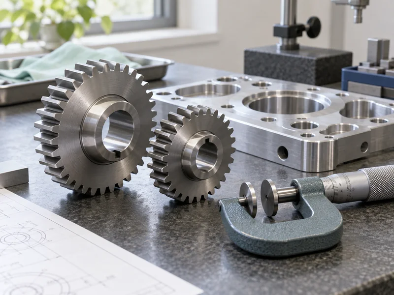
It should connect component measurements with the performance of the assembled reducer. Keep the material and process records, critical dimensions, assembly settings, lubricant condition, and test configuration together. This creates a traceable basis for deciding whether a later failure is a design issue or a manufacturing deviation.
An effective first-build sequence includes:
- Inspect the critical part relationships before assembly.
- Record fitted parts and any adjustments used during assembly.
- Measure free-running behavior and backlash over multiple positions.
- Apply representative loads while observing displacement and temperature.
- Repeat the initial checks after the defined duty-cycle test.
GIAN’s preinstallation gear motor checks support the basic functional portion. A custom reducer qualification should add the measurements that address its particular design risks.
How Should a Failed First Assembly Be Investigated?
Preserve the assembly condition before changing parts or adding clearance. Record where resistance occurs, whether it repeats with angular position, and how it changes when the reducer is mounted. Uncontrolled adjustments can remove the symptom while destroying the evidence needed to correct the drawing.
Compare the measured parts with the intended tolerance relationships. A part can meet its own drawing while the combined tolerances still allow an unacceptable assembly. That finding calls for a design review, not simply a request that the supplier manufacture more carefully.
What If Every Part Is Within Tolerance?
Review the tolerance stack, datum scheme, assembly deformation, and operating assumptions. Check whether heat treatment, coating, lubricant, or fastener settings introduce effects that were omitted from the original analysis. The drawing may need a functional requirement that the initial component dimensions did not capture.
Use a controlled change to test the suspected cause, then repeat the relevant measurements. Keep successful adjustments in a revision record and translate them into an inspectable requirement or documented assembly step. A handwritten instruction to make it feel smooth is not a repeatable manufacturing control.
This approach makes the first prototype valuable even when it fails. Its purpose is to reveal which assumptions need correction before the process is repeated across a larger batch.
What Makes a Supplier Discussion Productive?
Send the operating requirements, packaging model, datum concept, critical relationships, and proposed acceptance tests together. Identify which requirements are firm and which can change to improve manufacturability. This gives a supplier room to propose a practical solution without guessing the function of every tight dimension.
For a robot application, GIAN’s motor and transmission application team can be approached with the complete joint requirement. The most useful drawing is one that makes the desired assembled behavior clear. Precision then becomes a controlled engineering outcome rather than a collection of unnecessarily expensive dimensions.