
A coreless DC motor and a PWM driver should be matched by their current behavior, not only by voltage and maximum amperage. Low winding inductance can permit substantial current ripple during each switching cycle. The useful validation therefore measures the waveform, checks heating under the intended duty and confirms that the driver can regulate the chosen motor.
This article focuses on a brushed coreless DC motor driven through its two terminals. A brushless motor with a coreless winding uses a different commutation arrangement, so its phase-current assessment must follow the relevant inverter topology.
Why Can Two Compatible Voltage Ratings Still Produce a Poor Match?
A supply rating describes only part of the electrical combination. During PWM operation, the winding experiences switched voltage, while its resistance, inductance and back electromotive force influence how current changes. Two motors connected to the same nominal supply can therefore produce different current waveforms.
Gian’s coreless DC motor information is a starting point for identifying the construction and intended performance. Request the winding resistance and inductance together with the conditions used to measure them. An inductance value without its measurement context can be difficult to compare across suppliers.
Also confirm what the driver regulates. A voltage-mode bridge that varies duty cycle is not equivalent to a driver with a closed current loop. Current limiting, current regulation and average supply-current reporting are separate functions that may have different response times.
The broader distinction between a motor driver and motor controller helps allocate these responsibilities. For ripple validation, identify the actual power stage and its behavior rather than relying on the name printed on the board.
Which Driver Details Influence Ripple?
Switching frequency matters, but it is not the only variable. Supply voltage, duty cycle, winding inductance and the bridge’s recirculation strategy all affect the voltage across the winding during a switching period. The off-time behavior can differ between driver designs.
A higher PWM frequency may reduce ripple in a particular arrangement, yet it can also affect switching losses and the available control behavior. Do not assume that selecting the highest menu value is always the best operating point. Follow the driver’s supported range and verify the resulting temperature and waveform.
Some drivers specify a minimum load inductance or recommend an additional series choke for certain motors. Ask the driver supplier how that requirement is defined and whether the proposed motor meets it. An added choke changes the electrical system and should be evaluated for current rating, saturation, losses and control-loop compatibility.
Compare the electrical interface with the intended motor family. A brushless DC motor needs a commutating drive rather than the two-terminal brushed arrangement described here. A purchasing comparison should not group these products together simply because both are described as DC motors.
What Should Be Measured at the Motor?
Measure current in a single motor conductor using an appropriate current probe or a correctly implemented shunt measurement. A clamp placed around both outgoing and returning conductors will largely cancel the magnetic signal. Confirm the probe orientation, range, zero setting and bandwidth before relying on the trace.
Observe enough switching cycles to identify the ripple shape, then use a longer capture to examine startup and load changes. A single oscilloscope screenshot cannot show every timescale. Save the acquisition settings with the waveform so a second test can reproduce the measurement.
Record motor-terminal voltage where it is needed to interpret current behavior. Use measurement equipment and connections appropriate for the circuit’s voltage and switching environment. The test setup itself should not create an unintended ground path or materially change the circuit being evaluated.
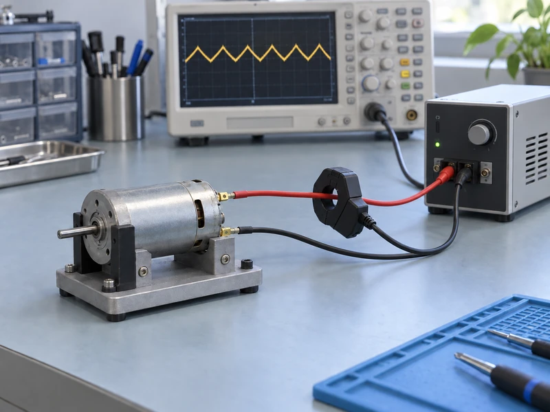
NIST’s explanation of metrological traceability emphasizes the documented connection between a measurement result and its reference. For this test, keep the calibration information and measurement uncertainty relevant to the current result, rather than treating an instrument label as the entire evidence package.
The current shown by a bench power supply is not necessarily the motor winding current. Switching and energy recirculation can make the two differ. Use the supply display for its intended purpose and measure the winding quantity directly when that is the acceptance criterion.
How Should Average, Peak and RMS Current Be Used?
Average current, peak current and RMS current answer different questions. A waveform with a moderate average can still have high peaks and a higher RMS value than a nearly smooth current of the same average. Each limit must be compared with the matching quantity.
For a simple illustrative waveform consisting of a DC level plus symmetrical triangular ripple, RMS current depends on both the DC component and the ripple amplitude. This explains why a low average reading alone cannot establish copper heating. Real waveforms should be evaluated from a suitable measurement rather than forced into an ideal model.
Review the current limits separately for the winding, power stage and any series choke. Match each specification to the measured quantity and its permitted duration. The winding’s transient allowance cannot be used to approve a peak that exceeds the bridge or choke specification.
Do not convert a waveform observation into a motor life claim without supporting evidence. Brush behavior, thermal conditions and the actual duty schedule can matter in a brushed assembly. The purpose of the ripple test is to establish compatibility under defined conditions, not to infer an unsupported service interval.
Which Operating Points Belong in the Trial?
Choose operating points from the intended application, including startup, low-speed operation, representative loaded motion and relevant supply extremes. The largest ripple or highest temperature may not occur at the nominal speed. Include transitions that the finished controller will actually command.
| Trial Condition | Evidence to Retain |
| Startup under representative load | Peak current, current-limit behavior and successful acceleration |
| Low-speed operation | Ripple waveform, regulation stability and temperature trend |
| Normal operating point | Average and RMS current with the required output load |
| Supply variation | Behavior at the approved voltage limits |
| Repeated duty cycle | Thermal result after the defined operating sequence |
Hold the mechanical load and mounting arrangement consistent when comparing drivers. A motor clamped to a large metal fixture may dissipate heat differently from one installed inside a compact product. Record the mounting and enclosure conditions alongside the electrical settings.
Define how long each condition runs and how thermal stabilization is assessed. A short demonstration can confirm basic operation but may miss temperature rise during repeated duty. Avoid reporting a continuous rating from a test that never represented continuous operation.
How Can a Problem Be Isolated Efficiently?
First challenge the measurement setup: confirm which conductor passes through the probe and whether the acquisition settings preserve the switching waveform. Identify whether the recorded quantity comes from a motor lead or the upstream supply connection. A second suitable sensing method can help resolve a doubtful trace.
Once the measurement is credible, vary a single supported drive parameter while retaining the same motor, supply and mechanical load. A permitted PWM-frequency adjustment is one possible trial. Record each configuration against its trace so the observed difference can be associated with that particular adjustment.
Gian’s coreless motor selection guide covers the broader motor requirements. Use those requirements to judge whether a proposed electrical adjustment still delivers the required speed, torque and duty, rather than optimizing the waveform in isolation.
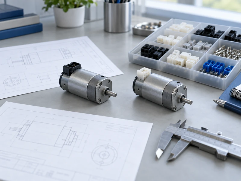
If a choke or a different driver is proposed, repeat the relevant electrical and thermal trials. Document the new component revision and control settings. The approved result belongs to that combination, not to every driver carrying a similar current rating.
What Should the Supplier Compatibility Record Contain?
Send Gian the motor operating points, selected power stage, supply range, PWM mode and captured current traces. Include the probe method, thermal test conditions and the acceptance limits used. This gives the engineering discussion a common set of measured facts.
Keep the distinction between construction and control explicit; Gian’s coreless and cored brushless comparison provides additional construction context. The final release should identify the exact motor and driver arrangement tested.
A useful compatibility decision states which operating envelope passed, what settings must remain fixed and which changes require another review. That record is more actionable than saying the motor runs on the available voltage, because it addresses the waveform and heat the motor actually experiences.