
For an OEM BLDC motor specification, rated speed should be the primary value when continuous performance at a defined torque matters. No-load speed describes operation without external shaft load and cannot establish loaded performance.
Engineers should state the voltage, controller settings, temperature, duty cycle, and measurement method behind each speed value before approving a motor drawing or purchase specification.
Rated RPM and Unloaded RPM Describe Different Operating Conditions
Both values are expressed in revolutions per minute (RPM), but they answer different engineering questions. A useful datasheet identifies the operating conditions rather than presenting either number as an isolated capability.
Rated Speed Defines a Specified Operating Point
Rated speed is the shaft speed associated with a declared operating point, usually including torque, voltage, and duty conditions. For continuous operation, the declared point must also satisfy the applicable thermal limits.
A motor described as operating at a particular rated RPM is not necessarily capable of maintaining that RPM at every torque. The rated value is meaningful only alongside its corresponding load and conditions.
The word “rated” should also be tied to a supplier-defined basis. Some documents use it for a nominal performance point; others intend a continuous operating limit. Confirm the definition before writing a purchase requirement.
For an illustrative calculation, a shaft delivering 0.08 N·m at 3,000 RPM produces mechanical power of approximately 25.1 W. The equation is P = 2πnT/60, where P is watts, n is RPM, and T is N·m. These are assumed values, not product specifications.
No-Load Speed Describes Operation Without External Shaft Load
No-load speed is measured with no intended external torque demand at the shaft. The motor still supplies enough torque to overcome bearing friction, windage, and other internal mechanical losses.
Because the external load is absent, no-load RPM can be useful for identifying unusual motor behavior or comparing controlled samples. It cannot verify speed under the application’s working torque.
A no-load result must identify whether the driver was commanding its maximum available speed or regulating to a lower target. Otherwise, two identical motors could report different RPM values simply because of controller settings.
How Do These Values Differ From Maximum Speed?
Maximum permissible speed is an operating limit, not another name for no-load speed. It may reflect rotor integrity, bearings, commutation capability, vibration, or other design constraints.
A controller may cap no-load RPM below that limit. Conversely, externally driving a motor can create overspeed conditions that its normal no-load test never reaches.
| Parameter | Meaning | Condition to Document | OEM Use |
| Rated speed | RPM at a declared torque and operating point | Torque, voltage, duty, temperature, cooling | Loaded-performance requirement |
| No-load speed | RPM without intended external shaft load | Voltage, driver mode, temperature | Characterization and reference inspection |
| Maximum permissible speed | Upper operating limit | Limit basis and allowed duration | Overspeed protection and operating boundary |
Which BLDC Motor Speed Value Should OEM Engineers Specify?
Use Rated Speed for Continuous Loaded Operation
If the equipment must operate steadily under torque, specify a required RPM at that torque. Add supply voltage, ambient conditions, mounting, cooling, and the duration for which the point must be sustained.
Do not mistake a catalog’s nominal rated speed for a guaranteed minimum under all conditions. A procurement specification needs an explicit acceptable range and a matching verification procedure.
Consider this hypothetical acceptance test: apply 0.08 N·m, allow the assembly to reach the agreed thermal state, and check that speed remains at or above 2,800 RPM with the specified supply. The numbers define a hypothetical acceptance point, not a Gian Transmission rating.
Where the application cycles between loads, define which condition is continuous and which is intermittent. An acceptable brief operating point may not be thermally sustainable throughout a long production shift.
Use No-Load Speed as a Secondary Reference
No-load RPM is worth recording when incoming inspection needs a quick, repeatable reference, particularly alongside no-load current. Such checks can reveal changes, but they do not diagnose every fault.
Different winding configurations can produce similar unloaded speeds while behaving differently under torque. Even a tightly matched no-load measurement cannot establish continuous torque capability, winding temperature, or shaft power.
Specify the unloaded test conditions separately from the loaded acceptance requirement. If no-load speed is used as a screening limit, document what happens when a sample falls outside that range.
Specify Multiple Operating Points When the Load Varies
A single rated point is insufficient when a mechanism demands high startup torque, variable running torque, or a minimum speed at reduced supply voltage. Define the application envelope instead.
- Continuous point: State working torque, minimum RPM, voltage range, duty duration, and cooling conditions.
- Intermittent point: Define torque, minimum speed, permitted duration, and recovery or rest conditions.
- Startup condition: Identify required breakaway torque and acceptable acceleration or starting time.
- Speed regulation: State allowable variation when the load changes inside the required range.
A torque-speed curve helps compare candidate motors across this envelope. Ask whether the curve represents steady operation, short-duration testing, or modeled performance before using it for selection.
For a fan-like load, required torque may increase with speed; for a positioning mechanism, the highest torque may occur during acceleration. Use the actual load profile rather than choosing a motor by the highest advertised RPM.
Why Can Rated Speed and No-Load Speed Differ?
Torque Demand, Back EMF, and Available Voltage
As rotor speed rises, back electromotive force increases. The driver must provide sufficient applied voltage to overcome back EMF and resistive and other electrical voltage drops while producing the required torque.
In a simplified operating region, more torque generally requires more current. Winding resistance then consumes more voltage headroom, so available speed may decrease under increased load when supply and control limits remain fixed.
That tendency is not a universal speed-drop formula. Winding characteristics, commutation strategy, current regulation, and voltage limits all affect the observed torque-speed relationship.
Motor Driver and Speed-Control Settings
A speed-regulating driver can increase commanded current as load rises, keeping the shaft near its target RPM until a limit is reached. A voltage-driven system without equivalent regulation may show a more obvious speed reduction.
Current limiting, PWM strategy, commutation timing, speed feedback, and maximum commanded RPM can change both measured values. Record the selected BLDC motor driver and its programmed settings alongside every speed measurement.
Comparing two motors tested with different control modes can confuse controller behavior with motor capability. Establish the driver settings before interpreting which design performs better at the required load.
Also record whether the test source can sustain the required input current. A bench supply entering current limiting may reduce speed even when the motor and its intended production supply would behave differently.
Temperature and Mechanical Load Conditions
Copper winding resistance increases with temperature. As the motor warms, its electrical operating point may shift, particularly where the controller has limited voltage or current headroom.
Couplings, bearing preload, seals, and gearbox losses also change the mechanical demand. A motor-only bench test may therefore differ from a measurement made after integration into the equipment.
For a geared assembly, specify the measurement location. An illustrative 30:1 reduction converts 3,600 motor RPM to approximately 120 output RPM by kinematic ratio; gearbox efficiency affects available output power and torque, not that ideal ratio itself.
How Should Rated Speed and No-Load Speed Be Measured?
Establish Consistent Test Conditions
Start with an agreed setup: supply measured at a defined electrical point, identified driver settings, motor direction, shaft connection, and an RPM instrument appropriate to the target speed range.
Record ambient temperature and, where meaningful, winding or housing temperature. Define whether readings are captured after a brief stabilization period or once temperatures reach a specified steady condition.
Optical tachometers, encoders, and Hall-based feedback can provide RPM, but each requires correct scaling. When converting measured electrical cycles to mechanical RPM, account for the motor’s pole-pair count and the signal being measured.
For electrical fundamental frequency f in hertz and p pole pairs, mechanical speed n = 60f/p in RPM. Raw Hall edges or commutation events are not automatically equivalent to one electrical cycle.
Fix the averaging interval and instrument resolution so that a changing display is not mistaken for unstable motor operation. Repeat measurements or include measurement uncertainty when the tolerance is narrow.
Where speed oscillates because of control-loop tuning, record the fluctuation as well as the average. A mean RPM inside tolerance may still conceal unacceptable variation for a precision-driven mechanism.
Measure No-Load Speed Without External Shaft Load
Disconnect the intended driven mechanism without removing normal components that belong to the tested motor assembly. Ensure the free shaft can rotate safely and that the sensor does not introduce meaningful drag.
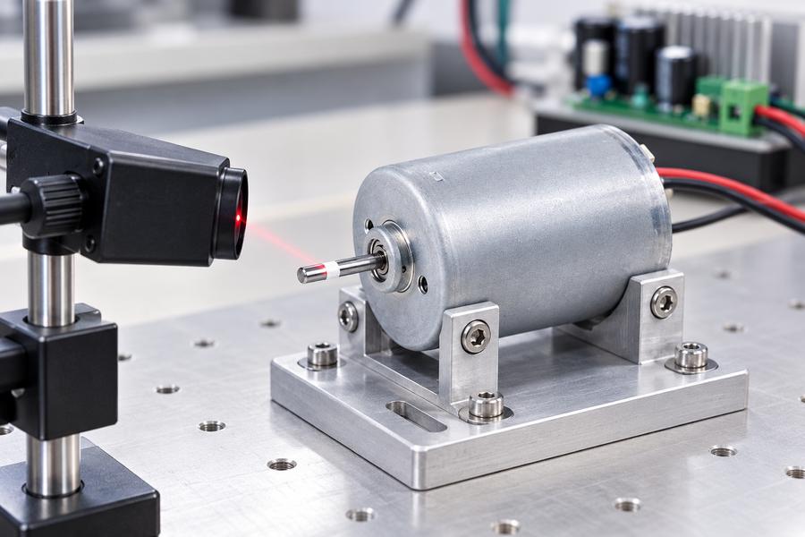
Illustrative no load speed measurement arrangement.
Apply the specified voltage and driver configuration, allow the RPM reading to settle, then record speed and no-load current. State whether the driver is speed-limited or operating under another defined command.
A low unloaded current with expected RPM can be a useful reference, but it does not prove the rotor will meet its torque requirement. Equally, a different unloaded reading deserves investigation rather than an automatic fault diagnosis.
Measure Rated Speed at the Specified Torque
Use a calibrated dynamometer or other controlled loading method to apply the required shaft torque. Measure torque and speed at the same shaft location or account explicitly for intervening transmission losses.
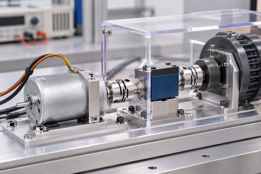
Illustrative rated load speed test arrangement.
Capture RPM, torque, voltage, and current concurrently. Where electrical input power is reported, define how it was measured; motor mechanical output power is shaft torque multiplied by angular velocity.
Verify the duty duration and temperature criteria associated with the claimed rated point. A speed recorded shortly after startup cannot, by itself, establish continuous thermal capability.
Where a speed range is specified, test at the relevant operating extremes rather than only at nominal voltage. Never force the motor beyond its agreed electrical, thermal, or mechanical limits to complete a test.
Compare Results Against the Required Operating Point
Present the two measurements separately, with conditions attached to each. For variable-load applications, add several loaded points to show how the system responds across the intended operating envelope.
A difference such as no-load RPM minus loaded RPM is descriptive, not a universal measure of motor quality. The amount depends on the test point and controller operation.
| Test Item | No-Load Test | Rated-Point Test | Acceptance Question |
| Mechanical condition | No intended external shaft load | Defined shaft torque | Is the load applied at the agreed location? |
| Electrical condition | Specified voltage and driver settings | Specified voltage and driver settings | Are limits and control mode recorded? |
| Measurements | RPM, current, voltage | RPM, torque, current, voltage | Are instruments and timing defined? |
| Thermal condition | Documented test temperature | Required duty and thermal state | Does the result support the claimed duration? |
| Decision | Compare with reference range | Compare with loaded speed requirement | Is the pass/fail rule documented? |
How Should OEM Buyers Write a Verifiable BLDC Motor Speed Specification?
Define the Electrical and Mechanical Requirements
Begin with the machine’s operating requirement rather than an available motor’s headline RPM. Define the shaft where speed matters, the corresponding load, and the voltage conditions expected in service.
Review custom brushless motor choices against the full application envelope. Gian Transmission lists design and voltage categories, but a category listing does not establish the electrical rating or stator construction of any particular pictured model.
- Speed requirement: State minimum, target, or acceptable RPM at each required torque point.
- Electrical supply: Identify nominal voltage, permitted variation, and where voltage is measured.
- Controller: Specify control mode, current limits, firmware settings where relevant, and speed command.
- Duty and environment: Define operating duration, ambient conditions, mounting, and cooling arrangement.
- Mechanical interface: Define shaft, coupling, gearing, output location, and acceptable transmission losses.
Establish Tolerances and Acceptance Criteria
A drawing that says only “rated speed: 3,000 RPM” leaves the supplier and buyer to guess the allowed deviation. Use an explicit range or minimum and attach the corresponding torque and test conditions.
Choose tolerances from the equipment’s functional needs and measurement capability, not from an assumed universal percentage. Include instrument calibration, stabilization criteria, and the number of repeated observations when needed.
Separate prototype design targets from production acceptance requirements. Define what happens if a sample fails: recheck the setup, inspect the motor, or apply an agreed disposition procedure.
If production sampling is planned, agree on lot definition, selection method, number of units, and disposition rules. A successful prototype test does not by itself define an adequate production quality-control plan.
For an illustrative acceptance statement: “At the defined shaft torque, specified supply voltage, and stated thermal condition, measured shaft speed shall remain within the approved RPM band.” Insert project-specific values only after validation.
Align Samples, Drawings, and Handover Records
Before release, confirm that the tested assembly matches the intended winding configuration, shaft arrangement, controller settings, and thermal installation. A passing result from a different configuration is not interchangeable evidence.
For questions about proposed custom configurations, use the Gian Transmission contact page to exchange the operating-point requirements and request the relevant technical documentation; do not treat a general category listing as a model-specific datasheet.
Identify the revision of each controlled document and link test results to the actual samples. Include instrument identification, calibration status, ambient and motor temperature, electrical setup, applied torque, measured RPM, and deviations.
The engineering handover should contain an approved operating-point table, a controlled test procedure, recorded sample results, and written acceptance criteria for rated speed and no-load reference checks.