
Reconnecting identical three-phase winding groups from star to delta changes an outrunner BLDC motor’s terminal electrical relationships, measured resistance, and ideal speed and torque constants. The coils, magnets, and mechanical construction remain unchanged.
Those ideal relationships require consistent fundamental and terminal-current definitions. Practical selection also depends on controller behavior, actual winding heating, accessible winding ends, and supplier-approved testing.
How Do Star and Delta Winding Connections Differ?
Star and delta describe how three existing winding groups are interconnected. They do not identify different motor constructions or require changing the number of winding turns.
Star (Y) Winding Arrangement
A star (Y) configuration joins one end of all three windings together, while their remaining ends serve as the three external phase terminals. The remaining three ends form the external motor terminals.
Because each terminal connects directly to one winding, terminal line current equals winding phase current. This relationship applies to the current flowing through that individual winding.
Under balanced sinusoidal fundamental conditions, each star-connected winding receives a phase voltage equal to the line-to-line voltage divided by √3. The corresponding relationship is Vphase = Vline / √3.
The neutral junction is commonly internal and may not be externally accessible. Its physical arrangement must be confirmed before considering any connection changes.
Delta (Δ) Winding Arrangement
In the delta arrangement, the three winding groups are connected end to end, creating a closed electrical loop. Each external terminal connects to a junction between two windings.
Each winding is therefore connected across two line terminals. Its fundamental phase voltage equals the corresponding line-to-line voltage under the balanced comparison.
For balanced sinusoidal fundamental currents, winding phase current equals terminal line current divided by √3. This relationship depends on the defined current components.
The closed delta circuit can also support circulating harmonic currents. Consequently, externally measured terminal current does not necessarily reveal every current component flowing inside the windings.
What Remains Unchanged After Reconnection?
A genuine reconnection retains the original winding groups, conductor dimensions, turns, rotor magnets, and air-gap geometry. Only the electrical connections between winding ends change.
The resistance of each individual winding remains fundamentally the same at an equivalent temperature. However, resistance measured between external motor terminals changes substantially.
The motor’s mechanical construction and magnetic design remain unchanged. Any revised performance capability must result from the new electrical operating conditions, not an assumed increase in magnetic strength.
How Do Resistance, Kv, and Kt Change Between Star and Delta?
Several important motor constants change when identical winding groups are reconnected. These relationships must be interpreted using consistent terminal measurements and clearly defined electrical conventions.
Line-to-Line Terminal Resistance
Let Rcoil represent the DC resistance of one winding group at a specified temperature. Each of the three identical groups has this same resistance.
With star connection, a DC measurement between two motor terminals passes through two windings in series. The measured terminal resistance is 2 × Rcoil.
With delta connection, one winding forms a direct path between terminals. The other path contains two series windings, producing an equivalent resistance of 2 × Rcoil / 3.
Therefore, the star terminal resistance is three times the delta terminal resistance. This is a connection effect, not evidence that the individual copper conductors changed.
Use the same winding temperature and suitable low-resistance measurement methods for comparison. Disconnect the motor from its controller to avoid unrelated circuit paths affecting results.
Speed Constant (Kv)
Kv describes mechanical rotational speed relative to a specified back-EMF voltage convention. Its numerical value depends on whether voltage is defined at winding or external terminals.
For identical winding groups, balanced fundamental back-EMF, and consistent line-to-line terminal voltage definitions, the ideal relationship is Kv_delta = √3 × Kv_star.
This means the delta configuration has a higher ideal terminal speed constant. At the same mechanical speed, its line-to-line fundamental back-EMF is lower.
The relationship should not be interpreted as a guaranteed increase in actual running speed. Applied voltage, load torque, controller limitations, and losses determine the operating point.
Torque Constant (Kt)
Kt relates generated electromagnetic torque to a defined current quantity. Comparisons require consistent terminal line-current conventions, sinusoidal fundamental assumptions, and equivalent current waveform definitions.
Under those matched conditions, the ideal relationship is Kt_star = √3 × Kt_delta. The star configuration produces greater electromagnetic torque per equivalent terminal line current.
However, the winding-current relationship also changes. Comparing torque constants expressed using winding phase current against constants expressed using terminal current produces misleading conclusions.
The rotor magnets and individual winding groups retain their underlying torque-producing characteristics. Reconnection changes how winding excitation appears at the external electrical terminals.
Why Measurement Conventions Matter
Motor datasheets and controllers may use different voltage and current definitions. Fundamental RMS, peak amplitude, phase current, and terminal line current are not interchangeable.
The familiar √3 relationships describe balanced sinusoidal fundamentals. They should not be applied directly to arbitrary PWM RMS readings or six-step current measurements without waveform qualification.
| Electrical Parameter | Star (Y) | Delta (Δ) |
| Winding arrangement | Three groups sharing a neutral junction | Three groups forming a closed circuit |
| Fundamental winding voltage | Vline / √3 | Vline |
| Fundamental winding current | Iline | Iline / √3 |
| Terminal DC resistance | 2 × Rcoil | 2 × Rcoil / 3 |
| Ideal terminal Kv | Kv_star | √3 × Kv_star |
| Ideal terminal-current-based Kt | Kt_star | Kt_star / √3 |
| Individual winding resistance | Rcoil | Rcoil |
The voltage and current relationships assume balanced sinusoidal fundamental components. Kv and Kt comparisons also require matching terminal conventions, while resistance relationships assume identical windings at equal temperatures.
What Changes in Real Operating Performance?
Ideal connection equations describe electrical scaling, but practical operating performance depends on the interaction between motor windings, controller behavior, supply voltage, and mechanical load.
Voltage Utilization and Loaded Speed
At a given mechanical speed, delta connection presents lower fundamental line-to-line back-EMF than star connection. This changes the voltage required for a particular operating condition.
Under suitable conditions, delta may allow operation at a higher electrical speed before reaching an inverter voltage constraint. However, the mechanical speed limit remains separately applicable.
Actual loaded speed also depends on winding impedance, current control, switching strategy, mechanical resistance, and torque demand. A higher Kv does not establish a guaranteed speed increase.
The intended speed range must be checked against rotor integrity, bearing conditions, controller electrical frequency, and the approved operating envelope for the complete assembly.
Torque Capability and Current Limits
For an equivalent electromagnetic torque under ideal balanced conditions, delta requires a different terminal current from star. This follows from the changed terminal-current-based torque constant.
The current flowing through each winding remains the more relevant quantity for evaluating conductor heating. Terminal current alone cannot establish the permissible thermal operating point.
At an equivalent winding current and magnetic operating condition, reconnection does not inherently increase the motor’s electromagnetic torque capability. The same winding groups produce the magnetic excitation.
Controller current limits may nevertheless affect which connection can deliver the required torque. Both the inverter’s line-current capability and the winding thermal limits must be evaluated.
Reconnection also does not create additional power capacity automatically. Any achievable power change requires supporting voltage, current, speed, cooling, and mechanical operating conditions.
Copper Loss and Delta Circulating Current
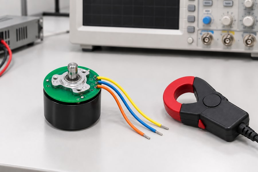
Plan current measurements around the quantity required: terminal current and winding current answer different questions. The unpowered equipment arrangement is illustrative, with no measured performance implied.
Resistive heating in the windings is determined by their electrical resistance and the true RMS current flowing through them. For three identical winding groups, total copper loss is 3 × Iwinding_rms² × Rcoil.
Iwinding_rms must represent the true RMS current through each winding, including relevant harmonic components. Using only a fundamental or externally measured current can underestimate heating.
Star and delta can have comparable fundamental copper losses at equivalent winding-current conditions. Their total operating losses may still differ because actual current waveforms change.
A closed delta circuit can support circulating currents driven by suitable harmonic electromotive forces. Such currents may increase winding heating without producing corresponding useful torque.
Some circulating components cancel at the external terminals. Therefore, terminal current measurements alone may not detect additional internal delta current or accurately establish total copper loss.
PWM and Harmonic Effects
Practical BLDC controllers apply switched voltage waveforms rather than ideal continuous sinusoidal voltages. PWM behavior, modulation strategy, and winding inductance influence the resulting current.
Six-step commutation can introduce substantial harmonic components, while sinusoidal control also experiences switching-related ripple. The resulting winding RMS current depends on the operating conditions.
Delta circulation is particularly relevant when harmonic back-EMF components can drive current around the closed winding circuit. Its significance depends on the actual motor design and waveform.
Engineers should compare measured current waveforms, electrical power, and winding temperature under representative operation. Ideal terminal constants alone cannot establish efficiency or thermal equivalence.
Can the Same Outrunner BLDC Motor Be Reconfigured?
Star and delta are alternative electrical arrangements, but not every assembled motor supports changing between them. Reconfiguration requires appropriate winding access and explicit supplier approval.
Verify Access to All Winding Ends
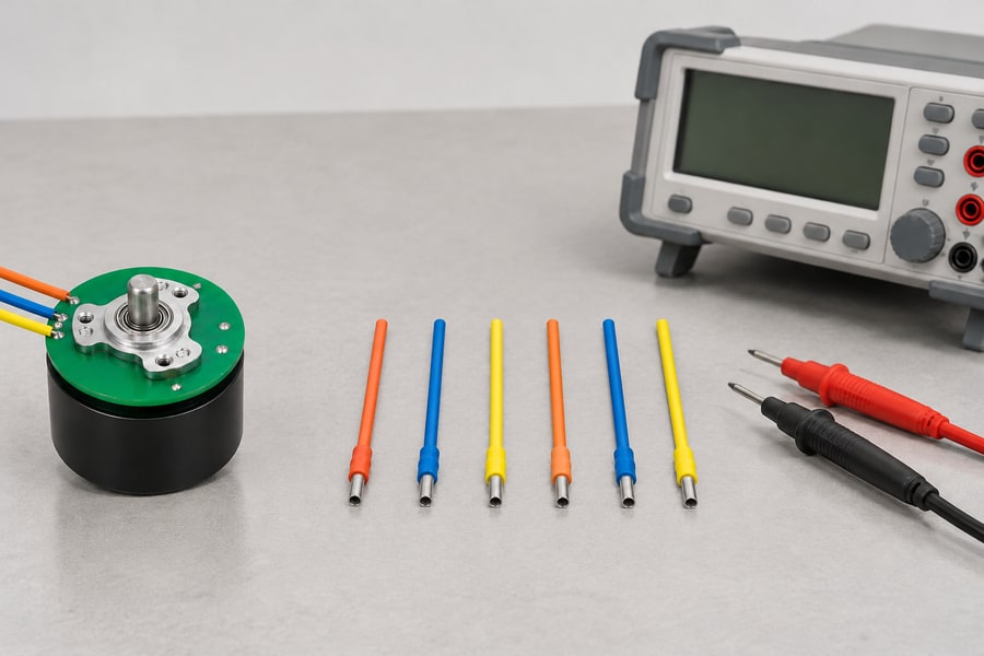
Separate wire samples illustrate the need to identify both ends of every winding group. They do not show the pictured motor as field-reconnectable; its actual termination drawing governs feasibility.
A three-phase motor has three winding groups, each with two ends. Reconfiguration generally requires accessible and identifiable connections to all six winding ends.
A motor with only three external phase leads may have its internal winding junctions permanently connected. Those terminals alone are insufficient for converting star into delta.
Swapping two external phase leads can change rotation direction in suitable configurations, but it does not alter the internal winding topology or electrical connection constants.
Even when six ends exist internally, physical accessibility does not establish field-reconfiguration suitability. Encapsulation, insulation arrangements, and mechanical construction can prevent an approved modification.
Review Physical and Electrical Requirements
The reconnection design must specify winding identification, terminal placement, connection joints, and insulation requirements. These details affect both electrical reliability and mechanical integration.
Inside an outrunner, connection wiring must remain clear of the rotating bell and shaft envelope. Routing must account for movement, tolerances, vibration, and thermal expansion.
Termination joints require suitable electrical contact, mechanical retention, and insulation. Any approved modification must preserve the intended protection against abrasion, contamination, and electrical faults.
Internal motor access can introduce risks involving permanent magnets, bearings, and delicate winding insulation. Unapproved disassembly may damage components or invalidate the intended construction.
Confirm Supplier Approval
Gian Transmission provides custom winding configuration options for its outrunner brushless DC motors. The feasibility of reconnection must still be confirmed for the particular design.
The review should identify the original winding arrangement, accessible winding ends, connection method, insulation details, and whether the motor was designed for reconfiguration.
Approval should also cover any required manufacturing or service procedures. A connection shown theoretically possible is not automatically suitable for modification after final assembly.
When reconnection is unsupported, separate factory-specified star and delta configurations may provide a more appropriate comparison than attempting to modify an assembled motor.
What Controller and Commutation Changes Must Be Checked?
Changing winding topology affects the electrical conditions presented to the controller. Existing drive parameters should not be assumed suitable merely because the motor uses the same external terminals.
Controller Voltage and Current Compatibility
The controller must accommodate the selected connection’s terminal back-EMF, current requirements, electrical frequency, and winding impedance throughout the intended operating range.
Current-control settings require particular attention because the relationship between terminal current and winding current changes. Identical current limits may produce different winding operating conditions.
Review the available DC bus voltage and modulation strategy against the required speed-torque profile. Include acceleration demands rather than evaluating only steady-state operation.
Protection settings must reflect the approved motor-controller combination. Overcurrent, undervoltage, and thermal responses should be evaluated using the selected connection and actual measured behavior.
Hall Sensor and Phase Mapping
Hall sensors provide rotor-position information used by compatible controllers for commutation. Their physical locations remain unchanged when the winding connections are modified.
However, the effective relationship between external phase terminals, winding excitation, and Hall signals may change. Existing commutation mapping therefore requires verification.
Engineers should check Hall-state sequence, terminal phase identification, commanded direction, and electrical alignment. Incorrect mapping can cause poor startup, torque pulsation, or excessive current.
Where necessary, recommission the controller using approved alignment and commutation procedures. Do not assume the original timing settings remain correct solely because sensor hardware is unchanged.
Startup, Reversal, and Protection Settings
Startup behavior provides useful evidence of correct phase mapping and adequate current control. Test the intended starting load using an approved operating procedure.
Acceleration and deceleration profiles must remain compatible with available torque and current. Reversing operation additionally requires assessment of mechanical inertia and transient electrical loading.
During deceleration, regenerative energy can affect the DC bus and protection behavior. The controller and supply arrangement must safely accommodate the specified duty.
Record the final controller settings alongside the winding configuration. These settings form part of the approved motor system rather than interchangeable defaults.
How Should Star and Delta Configurations Be Tested and Compared?
A reliable comparison separates the effects of electrical reconnection from changes in load, temperature, controller settings, and measurement technique. Both configurations require consistent test boundaries.
Establish a Controlled Comparison
Use the same winding groups, rotor, and mechanical assembly wherever an approved reconnection permits direct comparison. Otherwise, clearly document differences between factory-configured specimens.
Define DC bus conditions, controller operating mode, switching settings, and mechanical load before testing. Record which quantities represent instantaneous, average, peak, or RMS measurements.
Temperature should be recorded because copper resistance rises with heating. Resistance measurements taken at different temperatures must be normalized or interpreted with the temperature difference documented.
Instrumentation should distinguish terminal current from winding current where practicable. For delta configurations, use approved winding-current measurement methods or validated analysis to address circulating components.
All rotating tests require suitable guarding and approved operating limits. Test procedures must also address unexpected startup, stored electrical energy, and mechanical loading hazards.
Measure Electrical and Mechanical Performance
Begin with winding identification and disconnected terminal resistance measurements. Compare the results with the expected star or delta network relationships at the recorded winding temperature.
Measure fundamental back-EMF against mechanical rotational speed using the same terminal voltage definition. Determine Kv from consistent measurements rather than relying on controller speed estimates alone.
For torque testing, measure shaft torque and electrical current simultaneously under defined operating conditions. Record whether current values represent terminal fundamentals or actual winding RMS quantities.
Compare the required operating speed and load torque with measured electrical input and winding heating. Ensure each result corresponds to a clearly defined test condition.
Thermal verification should include representative continuous and intermittent duty. Stable operating temperature and allowable transient heating must be evaluated against application-approved component limits.
For delta connection, assess circulating-current effects through appropriate current measurements, waveform analysis, and thermal evidence. Externally balanced terminal currents do not establish the absence of internal circulation.
Finally, test startup, controlled acceleration, steady operation, deceleration, and reversal where applicable. Confirm repeatable commutation and protection behavior across the specified operating envelope.
Define Application-Specific Acceptance Criteria
Acceptance criteria should follow the actual application’s voltage, load, operating speed, thermal requirements, and controller limitations. Universal pass limits are inappropriate for customized motor configurations.
The following checklist links each verification item to measurable evidence. Results should be reviewed against approved project requirements rather than unsupported assumptions about either winding topology.
| Verification Item | Measurement or Evidence | Acceptance Basis |
| Winding identification | Connection drawing, continuity measurements, and terminal identification | Approved winding configuration |
| Terminal resistance | Temperature-referenced line-to-line DC measurements | Expected connection relationship and approved winding balance |
| Back-EMF and Kv | Measured fundamental terminal voltage and mechanical speed | Approved motor constant and speed requirements |
| Torque-current relationship | Measured shaft torque and defined electrical current | Required torque across the operating range |
| Winding current and heating | True winding RMS current and representative temperature measurements | Approved winding and component thermal limits |
| Harmonic and circulating-current effects | Current waveform analysis, suitable internal-current evidence, and heating | Approved loss and thermal performance requirements |
| Controller and Hall compatibility | Verified phase mapping, commutation alignment, and protection behavior | Approved controller operating requirements |
| Loaded operating performance | Speed, torque, input power, and temperature under representative duty | Application-defined operating envelope |
| Startup and reversal | Recorded starts, acceleration, deceleration, and direction changes | Specified functional and protection requirements |
Finalize the Approved Configuration
The final selection should reflect measured application performance rather than assuming one topology is universally superior. Voltage utilization, winding heating, and controller compatibility must agree.
For a custom project, Gian Transmission’s brushless DC motor engineering review can address the specified winding connection and its integration requirements.
The engineering record should identify the selected topology, winding identification, terminal definitions, resistance values, back-EMF convention, and approved controller operating parameters.
Include measured torque-speed performance, current definitions, thermal observations, commutation verification, and any restrictions identified during representative testing under the intended duty.
The required deliverables are a supplier-approved winding connection drawing, verified electrical specifications, documented controller settings, application-defined operating limits, and signed-off installation and acceptance-test records.