
A 5V BLDC application can tolerate only the drop remaining between its worst-case source voltage and required controller input, after transient and design reserves. The 5V label provides no universal percentage allowance.
OEM engineers should calculate round-trip wire and connector losses using DC bus current, then measure startup voltage dips and undervoltage recovery at controller terminals.
How Much Wiring Voltage Drop Can a 5V BLDC System Actually Allow?
The useful answer is a voltage budget, not a percentage of the nameplate voltage. Establish what reaches the controller under the most restrictive operating condition, then allocate the remaining margin.
Start with the Minimum Available Source Voltage
A supply labeled 5V may deliver less than 5V when manufacturing tolerance, regulation error, load, and temperature are considered. Its guaranteed minimum must come from the actual supply design.
Define where that voltage applies. A minimum specified at the supply terminals is different from a reading taken after a connector, fuse, or distribution trace. Otherwise, losses can disappear from the budget.
Battery-powered equipment needs the minimum source voltage over its permitted discharge range. For regulated supplies, examine the lowest output under the applicable input, temperature, and load conditions.
Establish the Required Controller Input
The controller must receive enough DC bus voltage to remain enabled and deliver the requested motor performance. A controller may remain enabled yet fail to deliver the required shaft performance, so test the operating-voltage requirement separately from its shutdown threshold.
Check the controller’s supported input range, undervoltage thresholds, and voltage needed for specified speed and load. The most restrictive verified requirement establishes the minimum used in the calculation.
A motor listed in a 5V category does not prove that every compatible controller accepts a 5V input. In particular, a controller specified for 12–48V cannot be assumed to run from 5V.
Subtract Transient and Design Reserves
When the source minimum represents a steady-state condition, a transparent first-pass budget is:
Vdrop,max = Vsource,min − Vrequired,min − Vtransient − Vreserve
Every term is a voltage in volts (V). The transient allowance covers voltage reductions excluded from the stated source minimum; the design reserve covers defined uncertainty or variation.
Do not subtract a source sag twice. If the measured minimum source voltage already includes the relevant startup dip, the separate transient allowance must exclude that same event.
Worked example using assumed values: Give the controller a 4.40V operating requirement and allocate 0.12V for transients plus 0.08V of design reserve. Let the source guarantee 4.75V at the stated measurement point.
The remaining harness budget is 4.75 − 4.40 − 0.12 − 0.08 = 0.15V. Those assumed values demonstrate the method; actual limits require the selected supply and controller specifications.
A 5% drop from nominal 5V would equal 0.25V, exceeding this illustrative 0.15V allowance. Another system could have a different budget, so 5% is not a universal limit.
If subtraction produces zero or a negative result, reducing harness resistance alone cannot create a positive voltage allowance. Revisit the supply, controller requirement, or system operating conditions.
How Do Wire Resistance and Connector Losses Affect a 5V BLDC Motor?
Once the allowable drop is known, calculate how much the power path consumes. The relevant path runs from the supply to the controller and back, through every series connection.
Calculate the Entire Supply-and-Return Resistance
The outgoing conductor and return conductor both carry bus current. A cable described as one meter long can contain approximately two meters of current-carrying wire in its loop.
For a simple two-conductor supply harness, Rwire,total = Rpositive + Rreturn. Each conductor’s resistance depends on material resistivity, actual length, cross-sectional area, and temperature.
Use wire resistance at the relevant operating temperature rather than relying only on room-temperature catalog values. Copper resistance rises with temperature, making warm-harness testing particularly useful.
If the return travels through a shared ground network, model the actual return path. Shared conductors can add load-dependent voltage shifts that a two-wire sketch conceals.
Account for Contacts, Crimps, and Intermediate Connections
Connectors create additional series resistance. Include both sides of mating interfaces, terminal crimps, splices, and other connections between the defined source and controller measurement points.
A seemingly small contact resistance matters when the available margin is measured in fractions of a volt. Poor crimping or contact deterioration can also increase heating and voltage loss.
Separate conductor and contact resistance during diagnosis. Replacing a cable with thicker wire will not repair a high-resistance terminal, and changing connectors will not shorten an excessive harness.
Use DC Bus Current, Not Motor Phase Current
For a DC supply harness, the basic resistive estimate is Vdrop = Ibus × (Rpositive + Rreturn + Rcontacts). Current is in amperes (A), resistance in ohms (Ω), and drop in volts (V).
The controller’s DC input current is not interchangeable with motor phase current. PWM switching and motor control can produce phase currents that differ substantially from the supply current.
Obtain bus-current values for the relevant operating points. Separate phase leads, if present between controller and motor, need their own loss and thermal analysis using appropriate phase-current information.
Illustrative resistance check: At an assumed 2.0A bus current, the 0.15V budget allows at most 0.075Ω total series resistance at that operating point.
Suppose the conductors contribute 0.045Ω and contacts 0.020Ω under the assessed conditions. The 0.065Ω total produces 0.130V drop, leaving only 0.020V against that illustrative budget.
These numbers are arithmetic examples, not recommended harness specifications. Verify the current profile, contact variation, and wire temperature before using any calculated margin for design approval.
| Parameter | Input to Obtain | Why It Matters |
| Source minimum | Voltage at defined source terminals, V | Starts the available-voltage budget |
| Controller minimum | Verified operational DC input, V | Sets the required destination voltage |
| Wire loop | Supply and return resistance, Ω | Captures both conductor losses |
| Connections | Combined series contact resistance, Ω | Captures terminals, joints, and mating interfaces |
| Bus current | Current at each evaluated operating point, A | Converts resistance into voltage drop |
| Reserves | Nonduplicated transient and design margins, V | Protects remaining operating headroom |
How Do Startup Transients and UVLO Affect the Voltage-Drop Limit?
A harness that passes a steady-load calculation can still fail during startup. Voltage changes quickly when controller demand, source response, and harness impedance interact.
Check the DC Bus Demand During Startup
Startup current depends on control strategy, acceleration, mechanical inertia, load, and current limiting. Do not substitute a motor’s phase-current limit for measured or modeled supply-side startup demand.
Evaluate more than the first energization. Acceleration against load, abrupt commands, and a restart after interruption may create different bus-current patterns and different minimum input voltages.
In the earlier illustrative harness, a hypothetical 3.0A bus current through 0.065Ω would create 0.195V of resistive drop. That exceeds the example’s 0.15V allocation before other dynamic effects.
This comparison flags a condition requiring evaluation; it does not predict a specific motor’s startup behavior. A real current waveform may vary over milliseconds, and the source voltage may move simultaneously.
Separate Resistive Drop from Dynamic Voltage Dips
Wire resistance contributes an approximately current-proportional loss, while harness inductance and source regulation can influence rapid transients. Bulk capacitance may briefly support the local DC bus.
A short pulse can have a different consequence from a sustained undervoltage. Capture voltage amplitude and duration together, rather than reducing the event to one minimum number.
For a complete brownout assessment, keep supply-terminal and controller-terminal records aligned. Their difference shows harness behavior; their absolute levels show whether the controller received adequate voltage.
Verify UVLO Trip and Recovery Behavior
Undervoltage lockout (UVLO) usually has a falling trip condition and a higher rising recovery condition, although implementation details vary. Use the actual controller documentation and settings.
After a dip, voltage rising above the trip threshold might not restart the controller. Recovery can require a higher threshold, an enable sequence, or another device-specific condition.
This distinction matters when a motor repeatedly starts, collapses the bus, stops, and starts again. The underlying issue can involve both wiring losses and source impedance.
Review the detailed BLDC motor brownout recovery considerations when defining trip, restart, and fault-clearing tests; verify behavior on the selected controller rather than assuming a universal sequence.
How Should OEM Engineers Measure and Validate Wiring Voltage Drop?
Measure the complete assembly, not only its individual cable parts. Production-intent wiring can reveal connection losses, return-path behavior, and transient effects missing from an idealized schematic.
Measure Both Ends of the Power Path
Record voltage at the supply output terminals and at the controller’s DC input terminals during the same operating event. The simultaneous difference estimates the drop across the included distribution path.
Specify measurement boundaries before interpreting results. If the source reading is taken before a fuse but the calculation excludes fuse resistance, the comparison will be inconsistent.
Use suitable differential measurements or independently referenced measurement equipment where necessary. Avoid oscilloscope grounding arrangements that unintentionally short separate points in the power system.
For very low harness resistance, four-wire Kelvin measurements can reduce lead-resistance error. De-energize and isolate the assembly as required by the measurement method and equipment.
Contact resistance may depend on how terminals are mated and loaded. Repeat measurements after representative assembly cycles when connection repeatability is part of the acceptance requirement.
Capture Startup and Peak-Load Waveforms
A handheld meter is useful for steady conditions but may miss short voltage dips. Use an oscilloscope with appropriate probing to capture controller voltage and DC bus current together.
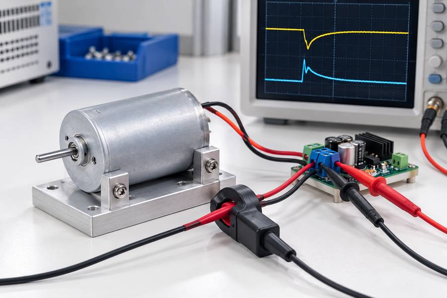
Illustrative harness test arrangement; motor and controller ratings must be confirmed for the selected assembly.
Trigger on startup or the expected lowest-voltage event. Include enough pre-event and recovery time to show whether the controller shuts down, recovers, or oscillates between states.
Switching edges can create narrow spikes unrelated to the sustained input voltage available to the controller. Apply documented measurement bandwidth and interpretation criteria rather than selecting arbitrary waveform extremes.
Match recordings to motor load, speed command, and controller state. Otherwise, a low-voltage trace provides little evidence about whether the required operating condition was achieved.
Test the Least Favorable Practical Combinations
At minimum, evaluate the lowest expected source voltage, relevant peak current, and elevated harness temperature. Include realistic cable length, connector configuration, and shared return loading.
Use production-intent parts and representative assembly methods. A carefully soldered bench harness may show lower resistance than the final crimped or removable connector system.
Verify not only voltage margin but also successful startup and required motor performance. Remaining above a UVLO threshold alone does not prove that speed and torque targets are satisfied.
Choose acceptance limits from the documented system budget. A universal percentage cannot replace requirements for both steady-state loss and permitted transient behavior.
| Test Condition | Measurements | Decision Supported |
| Continuous rated operating point | Source voltage, controller voltage, bus current | Steady-state margin and heating exposure |
| Startup under defined load | Voltage and current waveforms, controller state | Dip severity and successful enable |
| Highest relevant dynamic load | Minimum bus voltage and event duration | Transient margin during operation |
| Warm harness and connectors | Loop drop at defined current and temperature | Temperature-dependent losses |
| Minimum permissible source | Both endpoint voltages and delivered performance | Worst-case electrical operation |
| UVLO recovery trial | Trip, recovery, and restart sequence | Stable recovery without repeated resets |
How Can Wiring Voltage Drop Be Reduced in a 5V BLDC Application?
Apply changes to the loss mechanism actually found in testing. The best option may be larger conductors, better contacts, shorter routing, or a different power architecture.
Adjust Conductor Size and Route
Increasing conductor cross-sectional area reduces resistance for a given material and length. Shortening both the supply and return paths can deliver similar gains without changing the wire type.
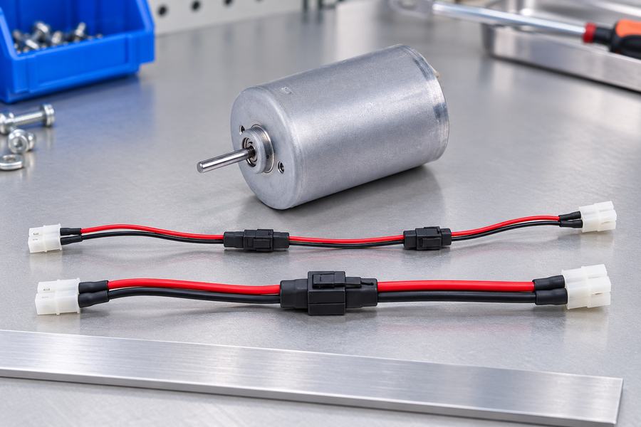
Illustrative harness test arrangement; motor and controller ratings must be confirmed for the selected assembly.
Check routing constraints before enlarging the conductor. Flex life, bend radius, connector termination compatibility, moving joints, and assembly space can restrict an otherwise attractive electrical choice.
Recalculate resistance at the expected operating temperature and confirm with an assembled harness. The objective is a verified voltage margin, not simply the largest feasible wire gauge.
Address High-Resistance Connections
A voltage measurement across each connector under load can reveal a disproportionate loss. This often directs action more effectively than replacing an entire harness without localizing the issue.
Choose contacts and terminations for the relevant current, environment, and assembly process. Control crimp tooling, terminal retention, and mating completeness through production inspection.
Fewer interfaces can mean fewer opportunities for series loss, but removability and service requirements may justify them. Set resistance acceptance criteria for the final configuration.
Review Supply Capacity and Local Energy Storage
If source voltage collapses at the supply terminals, changing the harness may not solve the dominant problem. Investigate source regulation, peak-current capability, and upstream impedance.
Local capacitors can support some brief current demands, subject to size, ESR, placement, and recharge behavior. They cannot eliminate the continuous Ibus × R loss of an undersized cable.
Relocating the controller closer to the supply may shorten DC wiring, but can lengthen motor phase leads. Evaluate the entire electrical and mechanical arrangement before moving components.
What Should an OEM Specify Before Finalizing a 5V BLDC Wiring Design?
An OEM specification should describe the complete power path and the required behavior at its ends. A nominal supply label alone is insufficient for design release.
Lock Down Electrical Operating Requirements
Document the minimum supply voltage at a defined point, controller input range, UVLO trip and recovery behavior, and bus-current profile across continuous and dynamic operating conditions.
State the load, speed, torque, and acceleration requirements used to determine the minimum usable bus voltage. If the motor performance requirement is stricter than UVLO, use that stricter limit.
Assign separate steady-state and transient acceptance criteria with measurement duration and bandwidth where relevant. Record precisely which voltage variations the reserve already covers.
Specify the Harness and Test Boundaries
Identify supply and return conductor lengths, material, cross-sectional area, connector types, termination methods, and expected operating temperatures. Include shared return paths where other loads alter current.
Define source and controller measurement terminals, instrument setup, and representative assembly conditions. These details make calculations reproducible and supplier measurements comparable.
Retain measured worst-case waveforms alongside tabulated resistance and voltage results. A pass/fail figure without operating context cannot support a later wiring or controller change.
Coordinate the Motor, Controller, and Handover Package
Gian Transmission lists custom brushless DC motor options, with electrical parameters and mechanical integration reviewed by model. A listed 5V category is not a promise about every configuration.
A slotless design option should likewise not be assigned to a particular motor without model confirmation. Neither design category establishes a controller’s input range or a harness voltage-drop allowance.
For an application-specific review, communicate the actual motor and controller selections rather than relying on category labels. The Gian Transmission contact page provides a route to share the relevant requirements.
- Electrical limits: Minimum source voltage, verified controller requirement, UVLO behavior, and separately defined reserves.
- Load profile: Startup, continuous, acceleration, and peak-load conditions with corresponding measured or justified DC bus currents.
- Harness definition: Supply and return lengths, conductor size, connections, temperatures, and resistance limits.
- Validation evidence: Calculations, endpoint voltage measurements, synchronized startup waveforms, and acceptance results from production-intent assemblies.
Release the wiring design only with a traceable handover package that identifies the tested hardware revision, worst-case voltage budget, measurement boundaries, controller settings, and agreed acceptance criteria.