
Reducing stepper motor idle current can lower heat during a pause, but the useful setting is the one that preserves the required position and restarts reliably. A percentage selected in a driver menu does not establish either condition. The motor, transmission, load and current transition need to be tested as one axis.
The practical question is how much current the stopped mechanism needs under its real disturbances. A horizontal inspection slide, a spring-loaded valve and a vertical carriage can produce very different answers even when they use the same motor frame.
What Does Idle Current Actually Control?
Idle current normally means the current supplied after the driver detects that motion commands have stopped for a specified interval. Some drivers express it as a fraction of run current, while others use separate registers, selectable modes or an enable input. Read the particular driver’s definition before comparing settings.
A reduced-current state is different from disabling the output stage. Disabling may remove electromagnetic holding torque altogether, leaving friction, detent torque and any separate brake to resist the load. Those remaining effects should not be treated as a position guarantee.
For a new axis, begin with the intended stepper motor and record its winding connection, rated current convention and available thermal information. A driver setting expressed as peak current is not interchangeable with an RMS winding-current rating without checking the definitions.
The driver also needs an explicit behavior description. A suitable stepper motor driver must support the required current transition, command interface and timing; its maximum current alone does not answer those questions.
Why Can Less Current Reduce Heat So Much?
Winding copper loss depends on current squared and winding resistance. As an idealized comparison at unchanged resistance, reducing current to 70% gives approximately 49% of the corresponding copper loss. This does not predict the same percentage reduction in motor surface temperature, because heat flow and other losses remain involved.
A motor that alternates between motion and long pauses may therefore benefit substantially from reduced holding current. A continuously moving motor with only short stops may show much less improvement. Record the actual operating schedule before estimating the potential benefit.
The University of Iowa’s stepper current-control tutorial explains how winding current is established and limited by different circuits. That background helps distinguish a commanded current setting from the electrical behavior actually produced. An idle-current decision still needs a test of the stopped mechanism.
Measure temperature at defined locations and with a consistent attachment method. A housing measurement is useful for comparing trials, but it is not automatically the winding temperature or proof that every internal component remains within its rating.
Which Loads Must the Stopped Axis Resist?
List the forces that remain after the move ends. Gravity, seals, springs, cable drag and externally applied process loads can all matter. Include disturbances that occur only occasionally, such as a neighboring mechanism engaging or an operator loading a fixture.
For a vertical axis, determine the machine’s required load-retention arrangement separately from current optimization. A brake, counterbalance or other engineered provision may be required by the application. Reduced current should not become the only assumed protection against a falling load.
The stopped equilibrium can also shift before obvious loss of synchronism occurs. A rotor may settle at a different angle when current changes, and the transmission may turn that small angular change into measurable output displacement. A test that checks only whether the axis visibly drops can miss an unacceptable positioning error.
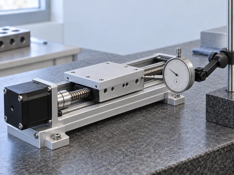
Use an independent position measurement at the point that matters to the process. If the requirement concerns a nozzle tip, measuring only the motor shaft can overlook compliance in the coupling, screw or structure.
How Should the Current Transition Be Tested?
Start with a documented reference condition using the approved run-current setting. Move to the test position, allow the normal settling interval, and record output position before and after the idle-current transition. Repeat the sequence at several positions and representative load states.
Change one parameter at a time. Lowering current while changing acceleration, microstepping and the delay before reduction makes it difficult to identify the cause of a new position error. Preserve the reference configuration so the comparison can be repeated.
Record the actual transition delay rather than relying on the name of a menu option. A driver may start its timer after the last step edge, after an internal motion state changes or after a communication command. Those events need not coincide with the machine’s definition of a completed move.
A useful initial trial sequence is:
- Reach the target using the production motion profile.
- Measure settled position before current reduction.
- Measure any displacement as the reduced state begins.
- Apply the defined stationary load or disturbance.
- Restore motion and measure the first subsequent destination.
Use the same observation interval for each candidate setting. A unit that remains still for one second has not demonstrated stability through a twenty-minute production pause.
Which Measurements Belong in the Comparison?
A current setting becomes useful engineering information when it is tied to a repeatable result. Keep the record compact enough that another technician can reproduce the trial. Include unsuccessful settings rather than retaining only the final preferred configuration.
| Recorded Item | Reason for Recording It |
| Run and idle current definitions | Prevents peak, RMS and percentage settings from being confused |
| Delay before reduction | Connects the electrical transition to mechanical settling |
| Position before and after transition | Reveals a shift that occurs without a complete missed step |
| Pause duration and applied load | Defines what the stationary test actually represents |
| Temperature and restart result | Shows whether the thermal benefit survives the next move |
Compare both cold and warmed operation. Friction, winding resistance and the surrounding structure can change as the assembly reaches its normal operating temperature. A setting that works at the beginning of a shift may have less margin later.
Record the measurement resolution and uncertainty alongside the allowable displacement. If the observed change is close to the measurement system’s capability, improve the setup before declaring the position stable. Repeating an inadequate measurement more often does not necessarily resolve its systematic error.
What Can Go Wrong on the First Move After a Pause?
The next move may begin before current has recovered sufficiently. A command sequence that works after a short pause may behave differently after the driver enters a deeper idle or sleep state. Check the specified wake-up behavior and confirm it in the actual controller sequence.
Some failures appear only when the first move opposes the standing load. Test both directions where the application uses them, and include the intended starting acceleration. A gentle manual jog is not a substitute for the production restart.
Use Gian’s explanation of stepper motor lost-step causes to separate restart torque limitations from wiring, acceleration and mechanical binding problems. Increasing holding current may hide another issue without correcting it.
Also inspect how the controller handles an interrupted pause. A new command, an enable change or a fault reset may take a different path through the driver than an ordinary restart. The validation sequence should cover the paths the machine actually permits.
How Should a Production Setting Be Released?
Choose the setting against written acceptance criteria for temperature, stationary displacement and restart position. Do not select the lowest tested current simply because one sample survived it. Allow for the expected variation in load, ambient conditions and production assemblies.
The release record should identify the motor revision, winding connection, driver revision, current mode and controller timing. Gian’s guide to choosing a stepper driver provides broader selection context, while this test record establishes the specific idle behavior of the chosen combination.
Lock the approved parameters into the production configuration and define who may change them. A replacement driver with a similar part description may use a different current scale or idle algorithm. Verify the relevant behavior before treating it as equivalent.
Finally, document the conditions that trigger another review: increased payload, longer pauses, a revised transmission, a different enclosure or changed restart acceleration. The broader stepper control methods remain useful background, but the approved idle-current setting belongs to the tested machine configuration.
For a supplier discussion, send Gian the pause schedule, standing load, permitted output movement and first-move profile together. That information makes a thermal improvement request measurable and gives the engineering team a clear basis for evaluating the motor and driver combination.