Installing a DC gear motor without testing can lead to noise, overheating, weak torque, unstable speed, premature gearbox wear, or even equipment downtime. Before the motor is mounted into a machine, a simple inspection and performance test can help confirm whether the motor, gearbox, wiring, shaft, and load capacity are suitable for the application.
Why Testing a DC Gear Motor Matters
The motor provides rotation, while the gearbox reduces speed and increases output torque. Because the motor and gearbox work together, both electrical and mechanical performance must be checked before installation.
Testing before installation helps you:
- Confirm voltage and current are within the rated range
- Check whether the output speed matches the design requirement
- Detect abnormal noise, vibration, or gearbox damage
- Verify shaft rotation direction
- Reduce the risk of overheating after assembly
- Avoid installing a defective motor into finished equipment
- Improve batch production consistency
If motors are used in large production projects, testing samples before mass assembly is also useful for comparing quality from a dc gear motor manufacturer.
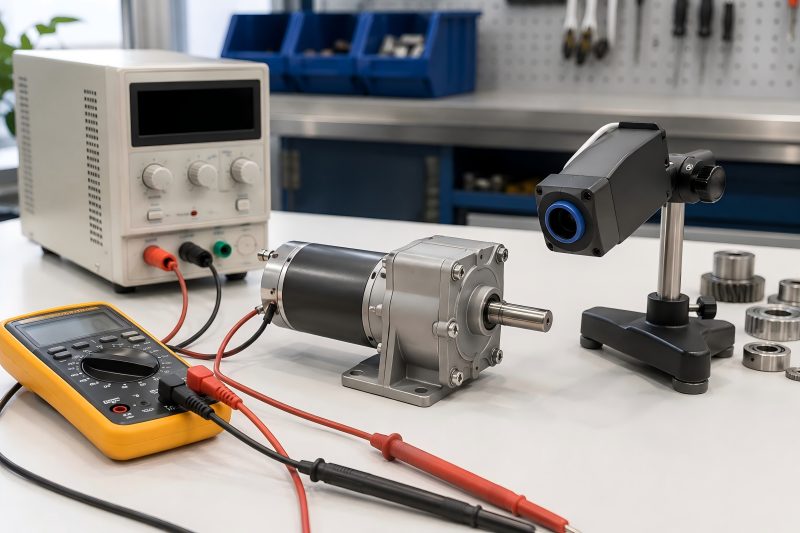
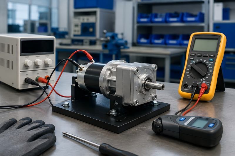
Basic Tools Needed for Testing
You do not need very complex equipment for basic DC gear motor inspection. Most pre-installation tests can be completed with simple tools.
| Tool | Purpose | Notes |
| DC power supply | Provides rated voltage to the motor | Adjustable power supply is preferred |
| Multimeter | Measures voltage, current, and resistance | Useful for wiring and electrical checks |
| Tachometer | Measures output speed | Contact or non-contact type can be used |
| Clamp meter | Checks running current | Useful for larger motors |
| Thermometer | Measures surface temperature | Infrared thermometer is convenient |
| Noise meter | Checks motor noise level | Optional for precision testing |
| Test fixture | Holds motor during testing | Prevents unsafe movement |
| Load device | Simulates working load | Used for torque or load testing |
Step 1: Check the Motor Label and Specifications
Before powering the motor, read the motor label or datasheet carefully. Confirm that the motor model matches your order and project requirements.
Key information to check:
- Rated voltage
- No-load speed
- Rated speed
- Rated torque
- Gear ratio
- Rated current
- Stall current
- Shaft diameter
- Shaft length
- Rotation direction
- Duty cycle
- Mounting hole size
- Connector or wire type
For example, if the equipment design requires a 12V motor but the actual motor is 24V, the motor may run too slowly or fail to deliver enough torque. If a 12V motor is connected to 24V power, it may overheat or burn out quickly.
Step 2: Inspect the Motor Appearance
A visual inspection helps identify shipping damage, assembly defects, or obvious quality issues.
Check the following points:
- Motor housing is not dented or cracked
- Gearbox case is not damaged
- Shaft is straight and not bent
- Wires are not loose, broken, or exposed
- Connector is clean and firmly attached
- Mounting holes are complete and accurate
- Output shaft has no rust or heavy scratches
- Gearbox has no oil leakage
- Nameplate information is clear
You can also gently rotate the output shaft by hand. Some resistance is normal because of the gear reduction system, but the shaft should not feel stuck, loose, or rough.
Step 3: Check Wiring and Polarity
DC gear motors usually have two wires for basic positive and negative power input. Some models may also include encoder wires, brake wires, signal wires, or speed control wires.
Before testing, confirm the wiring diagram. Wrong wiring may cause reverse rotation, unstable operation, encoder failure, or electrical damage.
For a basic two-wire DC gear motor:
- Connect positive power to the red wire
- Connect negative power to the black wire
- Reverse the polarity to change rotation direction
If the motor includes an encoder, do not connect encoder wires directly to motor power. Encoder wires usually need a separate low-voltage signal circuit.
Step 4: Measure Coil Resistance
Before applying power, use a multimeter to measure resistance between the motor terminals. This helps detect short circuits or open circuits.
Possible results:
- Very low resistance may indicate short circuit risk
- Infinite resistance may indicate an open circuit
- Stable resistance value usually means the winding is connected properly
Small DC motors often have low resistance, so the exact value depends on motor size, voltage, and winding design. Compare the measured value with the datasheet or a known good sample.
Step 5: Run a No-Load Test
A no-load test is one of the most important checks before installation. During this test, the motor runs without any external load.
Testing method:
- Fix the motor securely on a test bench.
- Set the power supply to the rated voltage.
- Connect the motor wires correctly.
- Start the power supply.
- Observe motor startup, speed, noise, vibration, and current.
- Run the motor for several minutes.
- Check whether the temperature rises abnormally.
A good DC gear motor should start smoothly, run steadily, and produce no harsh mechanical noise.
| Test Item | Normal Result | Possible Problem If Abnormal |
| Startup | Starts quickly and smoothly | Weak winding, gearbox jam, wrong voltage |
| No-load current | Close to rated no-load value | High friction, bearing issue, gear damage |
| Speed | Stable and near datasheet value | Wrong gear ratio, low voltage, motor defect |
| Noise | Smooth gear sound | Gear wear, poor assembly, lack of lubrication |
| Vibration | Low and stable | Bent shaft, unbalanced rotor, gear misalignment |
| Temperature | Slight increase only | Overload, internal friction, electrical fault |
Step 6: Measure No-Load Current
No-load current is the current drawn when the motor runs without load. This value is important because it reflects internal friction and electrical condition.
If the no-load current is much higher than expected, possible causes include:
- Gearbox friction
- Poor bearing condition
- Motor winding problem
- Rotor rubbing
- Incorrect voltage
- Gear misalignment
- Lack of lubrication
A motor with high no-load current may still rotate, but it can overheat quickly after installation.
Step 7: Check Output Speed
Use a tachometer to measure the output shaft speed. Compare the measured speed with the rated no-load speed or rated load speed.
For example:
- Rated no-load speed: 100 RPM
- Measured no-load speed: 95–105 RPM
This is usually acceptable.
If the measured speed is much lower than expected, check:
- Power supply voltage
- Wire connection
- Gear ratio
- Internal motor condition
- Mechanical friction
- Motor load during testing
If the speed is much higher than expected, the gear ratio or motor model may not match your order.
Step 8: Confirm Rotation Direction
Rotation direction is important for many applications, such as conveyors, actuators, locks, pumps, and automation equipment.
Check whether the shaft rotates clockwise or counterclockwise according to the equipment design. If the direction is wrong, reverse the polarity for a basic DC motor.
However, if the motor is connected with a driver, encoder, or controller, direction control may depend on the control system. In that case, follow the wiring diagram instead of simply reversing wires.
Step 9: Listen for Abnormal Noise
A DC gear motor normally produces some sound because gears are meshing inside the gearbox. However, the sound should be smooth and consistent.
Abnormal noise may include:
- Clicking
- Grinding
- Scraping
- Knocking
- Sharp whining
- Intermittent gear impact
Possible causes include damaged gears, poor lubrication, gear misalignment, worn bearings, or foreign material inside the gearbox.
For quiet applications such as medical devices, home appliances, office equipment, and smart furniture, noise testing should be stricter.
Step 10: Check Vibration and Shaft Stability
Excessive vibration can affect motor life and machine accuracy. During testing, observe whether the motor shakes strongly or whether the output shaft wobbles.
Check for:
- Bent shaft
- Loose gearbox
- Poor bearing support
- Unbalanced rotor
- Gear eccentricity
- Loose mounting screws
- Poor coupling alignment
A small amount of vibration is normal, but strong vibration should be investigated before installation.
Step 11: Perform a Load Test
After the no-load test, a load test helps confirm whether the motor can operate under real working conditions.
A load test can be done by connecting the motor to a test fixture, brake device, pulley, belt, gear, or simulated machine load.
During load testing, measure:
- Running current
- Output speed
- Motor temperature
- Torque performance
- Noise under load
- Startup ability
- Stability during continuous operation
| Test Condition | What to Check | Good Performance Indicator |
| Light load | Smooth running and current change | Current rises slightly and speed remains stable |
| Rated load | Torque and temperature | Motor runs without overheating |
| Frequent start-stop | Startup reliability | Motor starts repeatedly without stalling |
| Reverse rotation | Direction switching | Smooth change without gear impact |
| Continuous operation | Heat and stability | Temperature stays within safe range |
Step 12: Check Temperature Rise
Temperature rise is a key indicator of motor reliability. During testing, run the motor for a set period and measure the surface temperature.
Common reasons for abnormal heating include:
- Excessive load
- High input voltage
- High current
- Poor ventilation
- Gearbox friction
- Wrong duty cycle
- Motor size too small for the application
The motor should not become extremely hot during a short no-load test. Under rated load, some heating is normal, but the temperature should remain within the allowed range in the datasheet.
Step 13: Test Start-Stop Performance
Many DC gear motors are used in applications that require frequent starting and stopping. Examples include vending machines, electric locks, robots, actuators, and automatic doors.
Test the motor by starting and stopping it several times. Observe whether it:
- Starts immediately
- Stops smoothly
- Produces impact noise
- Draws excessive startup current
- Shows unstable speed
- Has delay or hesitation
If the motor fails to start under load, the selected torque may be too low.
Step 14: Check Gearbox Backlash
Gearbox backlash refers to the small clearance between gear teeth. Some backlash is normal, but excessive backlash may affect precision.
Backlash is especially important for:
- Robotics
- Positioning systems
- Medical equipment
- Measuring devices
- Electric actuators
- Automation control systems
To check backlash manually, hold the motor body and gently rotate the output shaft back and forth. If the free movement is too large, the gearbox may not be suitable for precision applications.
Step 15: Inspect Mounting Fit
Before final installation, compare the motor dimensions with the equipment mounting position.
Check:
- Mounting hole spacing
- Shaft diameter
- Shaft length
- Shaft flat, keyway, or D-shaft shape
- Gearbox diameter
- Motor body length
- Connector position
- Cable outlet direction
- Clearance for heat dissipation
Even if the motor works well electrically, wrong mechanical dimensions can cause assembly problems.
Final Pre-Installation Checklist
Before installing the DC gear motor into equipment, confirm the following:
- Model and voltage are correct
- Appearance is clean and undamaged
- Wires and connectors are secure
- Coil resistance is normal
- No-load current is within range
- Output speed matches the requirement
- Rotation direction is correct
- Noise and vibration are acceptable
- Shaft is stable and straight
- Load test result is acceptable
- Temperature rise is normal
- Mounting dimensions fit the equipment
Testing a DC gear motor before installation is a simple but important step for improving machine reliability. A complete pre-installation test should include visual inspection, wiring check, resistance measurement, no-load operation, current measurement, speed testing, direction confirmation, noise inspection, vibration check, load testing, and temperature monitoring.
By testing the motor before assembly, equipment builders can reduce failure risk, improve production efficiency, and ensure the motor performs correctly in the final application.