
Outrunner BLDC mounting screws must fit the specified threads, clamp the intended joint, and remain clear of windings and rotating components. A screw that feels tight may still be incorrectly installed.
These seven checks help engineering and procurement teams verify dimensions, assembly methods, retention materials, and final condition before releasing a motor installation.
Check Mounting-Screw Thread Size and Specifications
Mounting-screw verification begins with the approved motor drawing, not the appearance of the supplied fastener. Similar-looking screws can have incompatible threads, strength properties, or installation requirements.
Verify Screw Diameter, Pitch, and Thread Form
Confirm the nominal screw diameter, thread pitch, and thread form against the specified mounting interface. A screw that begins threading into a hole is not necessarily compatible.
Thread tolerance classes also matter. Incorrect combinations can produce excessive clearance, binding, or damaged threads even when the nominal diameter and pitch appear correct.
Review the complete fastener specification before approving purchased screws. Relevant details may include:
- Thread dimensions: Confirm diameter, pitch, thread form, and tolerance requirements.
- Fastener material: Check material and strength class against the approved joint design.
- Surface treatment: Identify coatings or plating that may affect fit, corrosion behavior, and friction.
- Head configuration: Confirm the specified head style and compatible driving feature.
- Identification: Match purchased fasteners to the approved drawing revision and procurement specification.
Inspect incoming screws for damaged threads, burrs, corrosion, and inconsistent dimensions. Forcing an unsuitable screw into the mounting hole can damage the internal thread.
Confirm the Correct Motor Mounting Interface
Outrunner motors generally have a rotating outer rotor surrounding stationary stator components. Their mounting arrangements vary, so assembly personnel must identify which features are intended to remain stationary.
Confirm whether the approved interface uses threaded holes, clearance holes, a mounting flange, or a separate bracket. Verify hole quantity, spacing, orientation, and accessibility.
Gian Transmission provides customization options involving windings, shaft dimensions, and mounting configurations. These options make drawing-specific verification important when purchasing screws for a customized outrunner brushless DC motor.
Do not assume that screws used on an earlier motor revision will fit a modified mounting interface. Even small changes in bracket geometry can affect fastener selection.
Confirm Fastener Specifications Before Procurement Release
The procurement specification should identify the approved screw type clearly enough to prevent substitution based solely on nominal diameter or an informal part description.
Where alternative fasteners are proposed, engineering should review their dimensions, material properties, coatings, and assembly implications before purchasing or installing them.
Check Effective Thread Engagement and Blind-Hole Depth
Correct screw length depends on the assembled mounting stack and the usable threads inside the motor interface. Nominal screw length alone cannot establish acceptable engagement.
Calculate Effective Full-Thread Engagement
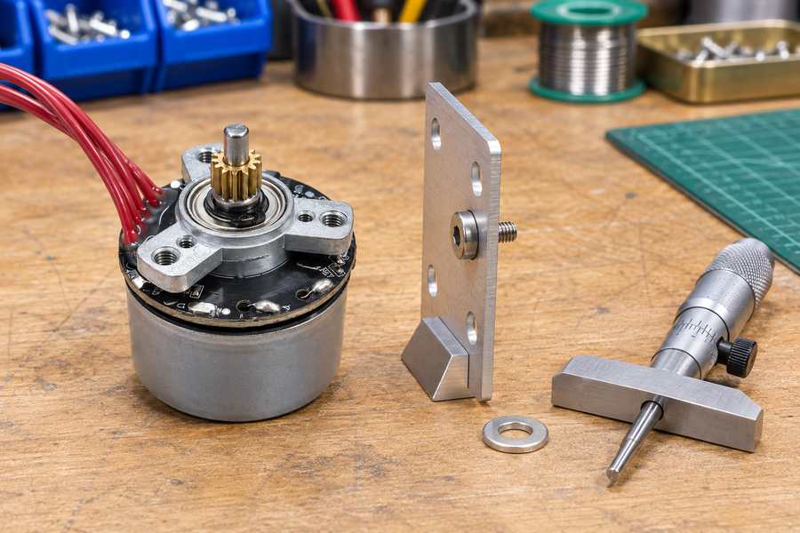
Start with the specified screw length and the thickness of every component positioned between its bearing surface and the threaded mounting interface.
These components may include mounting brackets, washers, spacers, and intermediate plates. The relevant measurement is the assembled grip thickness, including applicable tolerances.
For a typical screw measured from beneath its head, nominal penetration is determined by subtracting the assembled grip thickness from the screw length.
However, nominal penetration is not necessarily equal to effective full-thread engagement. Entry chamfers, incomplete threads, and screw-tip geometry can reduce the length of fully engaged mating threads.
Some head styles use different nominal length conventions. Confirm the applicable drawing definition before performing any subtraction or comparing screw lengths from different suppliers.
Assess both dimensional extremes. A thinner mounting stack combined with a longer screw increases penetration, while the opposite combination can reduce available thread engagement.
Distinguish Usable Thread Depth from Drilled-Hole Depth
Blind tapped holes commonly contain several different depth features. Confusing these dimensions is a significant source of mounting-screw selection errors.
The drilled cavity may extend beyond the complete internal threads. Its lower region can contain incomplete threads, unthreaded material, and a drill-point cone.
Therefore, the physical bottom of the drilled hole does not define the available length of complete load-bearing threads. The engineering drawing must distinguish these dimensions.
For screw-length verification, evaluate the following measurements separately:
- Drilled-hole depth: The physical extent of the drilled cavity, including relevant drill-point geometry.
- Usable threaded depth: The available depth of complete internal threads.
- Nominal penetration: The screw length entering the mounting interface after accounting for the assembled grip.
- Effective engagement: The portion where complete mating threads can carry the intended joint load.
- Bottom clearance: The remaining axial space before unacceptable screw-tip contact occurs.
Prevent Blind-Hole Bottoming
Bottoming occurs when the screw reaches a restrictive feature inside the blind hole before the joint receives its intended clamping force.
The obstruction may be the physical hole bottom, incomplete thread runout, or another internal feature. The screw can resist further rotation without properly clamping the bracket.
This condition is particularly misleading during assembly because the tool may indicate the specified torque even though the mounting surfaces are not adequately compressed.
Compare screw penetration, usable thread depth, and bottom clearance across the relevant dimensional tolerances. Engagement adequacy must also reflect the mating material and approved joint requirements.
| Dimension | Verification Method | Potential Problem |
| Screw length | Check specified measurement convention and tolerance. | Incorrect screw penetration. |
| Assembled grip thickness | Measure brackets, washers, and spacers. | Unexpected engagement variation. |
| Effective full-thread engagement | Evaluate complete mating-thread contact. | Insufficient load-bearing engagement. |
| Usable threaded depth | Verify the depth of complete internal threads. | Interference with incomplete threads. |
| Drilled-hole depth | Review cavity and drill-point geometry. | Overestimating usable thread depth. |
| Bottom clearance | Compare installed screw-tip position with limiting features. | Bottoming before proper clamping. |
There is no universal engagement length suitable for every outrunner mounting joint. Required engagement depends on fastener properties, mating materials, loading, and the approved design.
Check Screw-Tip Intrusion and Internal Motor Clearance
A mounting screw can satisfy thread-engagement requirements yet still extend into an internal motor space. This risk must be evaluated separately from blind-hole bottoming.
Identify Potential Intrusion Paths
Determine whether each mounting hole is fully enclosed or communicates with an internal motor cavity. Through-holes and open-ended threaded passages deserve particular attention.
A screw extending through such an opening may approach stationary windings, insulation, electrical connections, or the path of a rotating component.
Review the actual motor cross-section or approved internal clearance information. External mounting drawings may not reveal sensitive components immediately beyond the threaded interface.
Potential interference locations include:
- Stator windings: Exposed screw tips may contact conductors or damage winding insulation.
- Internal wiring: Screw penetration may interfere with routed wires or electrical connections.
- Rotor assembly: Protruding fasteners may enter the movement envelope of the rotating bell or magnets.
- Nearby components: Sensors, support structures, or other internal features may restrict available space.
Evaluate Rotor Movement and Tolerance Accumulation
Static screw-tip clearance is only one part of the assessment. Relevant rotor movement, bearing endplay, component positioning, and manufacturing tolerances can change available separation.
Evaluate the combined dimensional condition most likely to reduce clearance. The longest permitted screw, thinnest mounting stack, and closest internal component position may occur together.
Where axial movement or another permitted displacement affects separation, the clearance assessment should consider that movement rather than relying solely on nominal geometry.
Do not assume that a rotor turning freely by hand proves sufficient clearance under every operating condition. Required verification depends on the specific motor design.
Account for Customized Motor Configurations
Customized windings, shaft arrangements, or mounting features may change the internal geometry relevant to fastener penetration. An earlier configuration should not establish clearance for a revised design.
Procurement teams evaluating a customized brushless DC motor should obtain the applicable mounting drawings and clearance requirements rather than assume a standard screw length.
Controller and sensor integration may also introduce wiring or components near the mounting interface. Their actual locations must be checked when they affect the screw installation.
If internal geometry is unavailable, request engineering confirmation before installation. A convenient screw length is not evidence that winding or rotor clearance has been established.
Check Screw-Head Seating and Mounting-Stack Alignment
Even a correctly threaded screw cannot provide reliable clamping when its head seats incorrectly or the mounting stack contains gaps, misalignment, or damaged contact surfaces.
Verify Screw-Head and Bearing-Surface Compatibility
Check whether the selected head geometry matches the intended mounting surface. Flat-bearing, countersunk, and other head configurations distribute contact forces differently.
Incorrect head selection can concentrate pressure, damage the bracket, or prevent complete seating. Verify washer requirements against the approved design rather than adding washers automatically.
Where washers are specified, inspect their dimensions, hardness requirements, and contact surfaces. A washer must not obstruct neighboring parts or reduce thread engagement unexpectedly.
Also confirm external head clearance. On an outrunner assembly, screw heads or tools must not interfere with the rotating bell or other nearby moving hardware.
Inspect Mounting Brackets and Spacer Alignment
Inspect mating surfaces before tightening. Burrs, chips, coating buildup, and trapped debris can create a misleading contact condition or prevent the bracket from sitting flat.
Confirm bracket-hole positions and spacer orientation. Misaligned holes can introduce lateral loading or damage threads when screws are used to pull components together.
For assemblies using multiple screws, begin installation according to the approved procedure and check whether each fastener engages naturally before applying final tightening torque.
A mounting bracket should fit its intended interface without requiring excessive screw force to correct its shape or position. Resolve significant alignment problems before fastening.
Prevent Assembly-Induced Distortion
Uneven tightening or incorrect contact geometry can distort a mounting bracket or introduce unintended loads into the motor structure. The effect depends on joint stiffness and geometry.
Inspect the seated joint for visible gaps and abnormal contact. Where flatness or distortion limits are specified, use the approved measurement method.
Do not interpret the absence of visible gaps as complete proof of correct clamping. Seating inspection supports, but does not replace, the specified tightening process.
Check Tightening Torque, Tools, and Friction Conditions
Mounting-screw tightening must create the required joint condition without damaging the screw or threaded interface. An appropriate torque specification depends on more than nominal screw diameter.
Confirm the Approved Tightening Requirements
Use the torque requirements established for the actual fastener, mating material, and mounting joint. Avoid copying a tightening value from another motor configuration without approval.
Applied torque is not equivalent to clamp load. Friction at the screw-head bearing surface and between engaged threads accounts for a substantial portion of the applied tightening torque.
The remaining portion contributes to fastener tension, subject to the joint design and installation conditions. Consequently, equal torque readings do not guarantee equal preload.
Where preload is critical, the engineering specification should define an appropriate installation and verification method rather than relying on an assumed torque-to-tension relationship.
Verify Torque Tools and Tightening Procedures
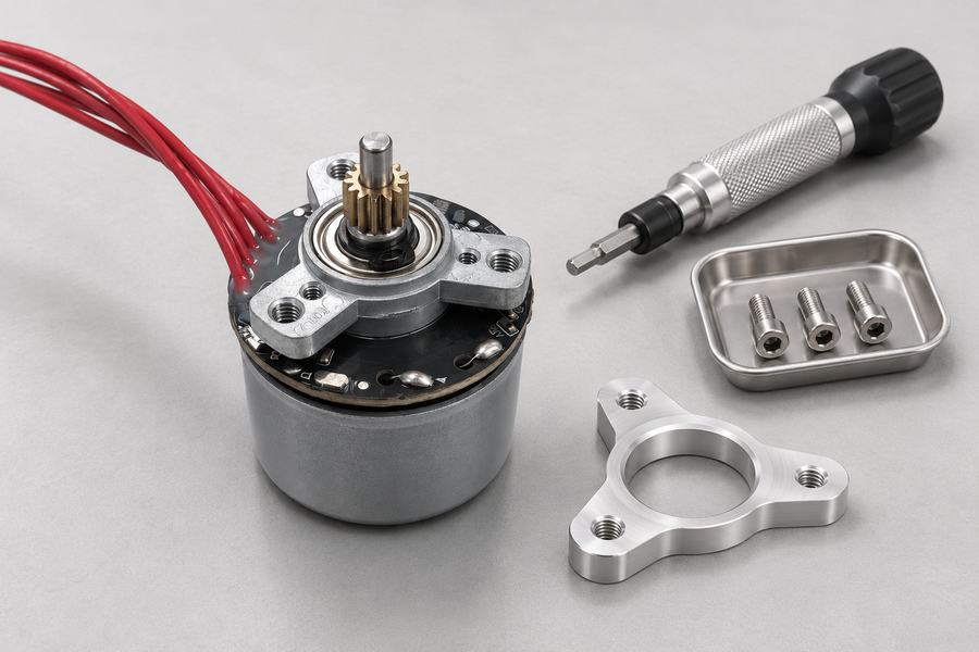
Confirm that the selected torque tool is calibrated and operates within an appropriate working range. Driver bits must properly engage the specified screw-head feature.
Damaged recesses, worn tools, or poor driver alignment can introduce installation errors. Replace unsuitable tooling rather than compensating through additional force.
For joints with several mounting screws, follow the specified tightening sequence. A staged or alternating sequence may be required to achieve consistent seating.
Inspect for abnormal resistance during installation. Unexpected torque behavior can indicate thread damage, incorrect engagement, contamination, or a seating problem requiring investigation.
Control Dry, Lubricated, and Coated Friction Conditions
Dry threads and lubricated threads can produce different clamp loads at the same applied torque. Coatings and locking compounds may also change friction behavior.
A tightening specification developed for one surface condition should not automatically be applied to another. Lubrication can increase preload at unchanged torque, potentially overstressing components.
Conversely, increased friction can consume more applied torque without producing the intended tension. Both situations make uncontrolled fastener substitution or surface treatment problematic.
Check the following process conditions before production assembly:
- Thread condition: Confirm cleanliness and the required dry or lubricated state.
- Surface treatment: Verify that supplied coatings match the approved specification.
- Tool control: Check calibration, driver condition, and operating range.
- Tightening sequence: Follow the specified order and any staged tightening requirements.
- Process acceptance: Record required results and investigate abnormal tightening behavior.
The objective is a controlled fastening process appropriate to the joint. Increasing torque to compensate for uncertain engagement or poor seating is not an acceptable correction.
Check Thread-Locking Methods and Material Compatibility
Motor vibration and changing mechanical loads may influence screw retention, but additional locking features should be selected through the joint design rather than assumed necessary everywhere.
Select an Appropriate Screw-Retention Method
Determine whether the approved assembly requires a thread-locking compound, a prevailing-torque fastener, another mechanical retention feature, or no additional locking method.
The selection should consider vibration exposure, service temperature, mating materials, maintenance access, and the joint’s required disassembly procedure.
Some locking arrangements alter installation friction or introduce prevailing torque. Their presence may require a specific tightening method or acceptance procedure.
A locking feature does not correct inadequate engagement, incorrect screw length, damaged threads, or poor clamping. Those conditions must be resolved independently.
Verify Locking-Material Compatibility
Where a liquid thread-locking compound is specified, confirm compatibility with the screw coating and the mating materials. Cure behavior and retention performance depend on application conditions.
Check the required service-temperature range and any cleaning or surface preparation instructions. Do not assume every compound behaves identically on different metallic surfaces.
Internal motor materials introduce additional concerns. Excess compound can migrate toward winding insulation, plastics, adhesives, sensors, or electrical connections if applied incorrectly.
Use the approved application location and quantity. Uncontrolled excess material should never be allowed to enter the motor cavity or contaminate sensitive components.
Verify Application and Future Maintenance Requirements
Follow specified curing conditions before handling or operating the completed assembly. Required cure time and process conditions must come from approved material instructions.
Check whether the locking method affects the defined torque procedure. A process qualified for dry threads may not remain valid after introducing a wet compound.
Consider future maintenance. Some retention methods require cleaning, replacement fasteners, or renewed compound following disassembly, while others introduce specific removal requirements.
Record the approved locking method and relevant application details when traceability is required. The documentation should clearly specify how the joint must be reassembled during maintenance.
Check Final Assembly Clearance, Verification, and Records
Final inspection confirms that the approved components were installed correctly and that the completed motor assembly satisfies the defined mechanical and process acceptance requirements.
Inspect the Completed Mounting Joint
Check that all specified screws are present, correctly positioned, and seated against their intended contact surfaces. Inspect the bracket for visible gaps or deformation.
Confirm that washers and spacers remain correctly located. Remove loose hardware and assembly debris that could enter the rotating motor structure.
Inspect nearby wiring and sensor connections for pinching, excessive tension, or contact with moving components. Cable routing must reflect the actual assembly configuration.
Review any witness marks or other assembly indicators required by the approved procedure. Such indicators support process control but do not independently establish clamp load.
Verify Rotor Movement and Mechanical Clearance
Perform mechanical inspections with the motor de-energized and hazardous movement controlled. Follow approved procedures before touching or manually moving any exposed rotor components.
Where permitted, controlled manual rotation may reveal obvious rubbing or obstruction. However, smooth movement cannot establish every internal clearance under operating conditions.
Additional verification may be necessary for assemblies with relevant axial movement, temperature-dependent clearances, or project-specific mechanical loading. These requirements must be defined by engineering.
Any powered functional check should use an approved procedure with suitable guarding, operating controls, and acceptance criteria. Never improvise an energized test around exposed rotating hardware.
Complete Inspection Records Before Assembly Release
The release record should identify the motor configuration, drawing revision, screw specification, and required inspection results. This supports traceability when customized assemblies are manufactured or serviced.
Record dimensional verification, tightening information, and locking-method details according to the approved inspection plan. Missing information should be resolved before release when required for acceptance.
| Inspection Item | Verification Method | Acceptance Basis |
| Thread specification | Inspect fasteners and review drawings. | Approved screw and mating-thread requirements. |
| Engagement and bottom clearance | Measure dimensions and evaluate tolerances. | Required engagement without bottoming. |
| Internal intrusion clearance | Review geometry and perform specified verification. | No unacceptable interference with motor components. |
| Screw-head seating | Inspect contact surfaces and bracket alignment. | Correct seating and mounting condition. |
| Tightening process | Review tool status and assembly records. | Approved tightening procedure completed. |
| Thread locking | Check material, application, and process records. | Approved retention requirements satisfied. |
| Final mechanical condition | Perform safe mechanical and required functional checks. | No unacceptable interference or assembly defects. |
| Documentation | Review inspection and deviation records. | Required evidence complete and deviations resolved. |
Resolve Nonconformities Before Final Release
Unexpected screw penetration, damaged threads, abnormal tightening behavior, or mechanical interference should trigger a documented evaluation rather than an informal assembly adjustment.
Corrective actions may involve selecting an approved fastener, restoring a mounting surface, replacing damaged components, or revising the installation procedure through engineering control.
After correction, repeat the inspections affected by the change. A replacement screw or altered bracket can affect more than one previously accepted mounting condition.
Release the assembly only when the required checks are complete, applicable records are available, and identified deviations have been resolved through the approved process.