
Hall signals can look electrically healthy at a motor connector while a controller still commutates incorrectly because interface assumptions were never recorded.
An electrical interface sheet should define measurable sensor limits, connector references, rotor-angle conventions, and validated timing behavior, allowing engineers to distinguish wiring mistakes from genuine sensor or control faults.
Hall Sensor Supply Voltage and Ground Reference
The first interface requirement is the Hall sensor power supply. Engineers need to know which voltage the sensor circuit accepts and how that supply relates to the controller.
Specify the Supply Voltage and Current Requirements
Record the nominal Hall supply voltage, allowable operating range, and maximum supply current. These values must describe the actual sensor assembly rather than an assumed industry-standard arrangement.
The controller must maintain the required sensor supply throughout normal operation. Consider startup, motor acceleration, supply disturbances, and any operating conditions that affect available voltage.
A nominal voltage alone is insufficient because sensor operation depends on the voltage reaching the assembly. Connector resistance, cable losses, and supply tolerance can affect that voltage.
- Nominal supply voltage: Identify the intended sensor power supply and its electrical reference.
- Operating voltage range: Record the minimum and maximum permitted voltage at the sensor supply terminals.
- Supply current: Specify the expected and maximum supply requirements, including relevant output-loading conditions.
- Supply protection: Document applicable polarity, transient, and power-sequencing requirements without assuming protection components are installed.
Identify Sensor Return and Grounding Relationships
Identify the Hall sensor ground terminal and explain its relationship to the controller signal reference. The motor’s power-current return path and the Hall circuit’s signal reference may have different electrical requirements and should be identified separately.
Motor winding currents can create voltage differences across shared conductors. These differences may reduce logic noise margins when Hall signals use the same return path.
Document whether sensor return and motor power ground are connected internally, externally, or through an approved grounding arrangement. The interface drawing should identify the intended connection boundary.
Where shielding is required, distinguish the cable shield termination from the Hall signal return. Their connections should follow the approved grounding design rather than an arbitrary wiring convention.
Also define sensor behavior when supply power is absent while controller inputs remain energized. Any permitted input backfeeding or protection requirements must be established for the actual circuit.
Hall Output Type, Pull-Up Ownership, and Logic Thresholds
Hall outputs must be electrically compatible with controller inputs. A shared connector does not guarantee compatibility when output structures, pull-up arrangements, and logic thresholds are different.
Identify the Hall Output Circuit
The interface sheet should identify each Hall output as open-collector, open-drain, push-pull, or another documented circuit type. This determines how the output produces its logic levels.
Open-collector and open-drain outputs generally require an appropriate pull-up connection to establish a high level. Push-pull outputs actively drive their permitted high and low states.
For open outputs, identify who provides the pull-up resistor. It might be integrated into the motor assembly, installed in the controller, or supplied externally.
Unclear pull-up ownership can leave an output floating or create incompatible loading. Record the permitted pull-up voltage, resistor range, and current limits for the selected interface.
- Output structure: Identify the circuit type and active signal polarity for Hall A, Hall B, and Hall C.
- Pull-up ownership: State whether the motor assembly, controller, or external circuit supplies the required resistor.
- Output loading: Record applicable sink or source current limits and the conditions used to establish guaranteed logic levels.
- Electrical protection: Identify applicable input or output voltage limits, especially when connected circuits use different supply domains.
Separate Output Guarantees from Receiver Thresholds
The motor-side electrical specification should state guaranteed output-low voltage, VOL, and output-high voltage, VOH, under defined supply, temperature, and loading conditions where applicable.
These output characteristics are different from the controller receiver thresholds. VIL identifies the highest voltage guaranteed to be recognized as low, while VIH identifies the lowest recognized as high.
A compatible interface requires the worst-case output-low level to remain below the receiver’s permitted low threshold, with sufficient allowance for electrical noise and voltage differences.
Likewise, the guaranteed output-high level must exceed the receiver’s required high threshold. Both comparisons should use the applicable worst-case operating and loading conditions.
For example, an output that rises through a resistor may reach a suitable static high level but still require evaluation of its electrical loading and available noise margin.
Do not substitute typical voltage measurements for guaranteed limits. An interface that works on one laboratory assembly might fail across permitted component or operating variations.
If the voltage domains are incompatible, document the required level conversion or interface circuitry. Dynamic rise times, propagation delays, and filtering belong in the timing evaluation.
Connector Pinout, Contact Identification, and Viewing Orientation
A connector pinout must identify physical contacts without requiring technicians to interpret wire colors or guess which side of a connector drawing they are viewing.
Identify Every Connector Contact
Specify the connector identification, mating component, contact numbering, and keying arrangement. Distinguish the motor-side connector from the controller-side mating connector.
Assign Hall A, Hall B, Hall C, sensor supply, and signal return to individual contacts. Document any shield, drain, reserved, or intentionally unconnected contacts separately.
A contact shown as unused should not automatically be connected to ground. Its permitted treatment must follow the approved electrical design and connector documentation.
If multiple harness versions exist, give each version an identifiable drawing revision. Connector appearance alone cannot establish electrical interchangeability between different assemblies.
State the Mating-Face Viewing Direction
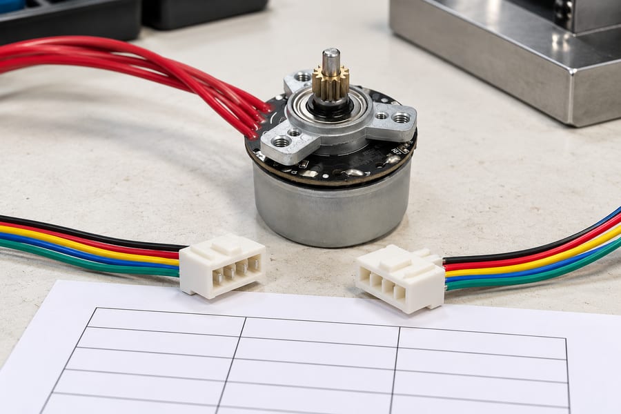
The connector arrangement is illustrative. Contact numbering, mating-face orientation and wire assignments must come from the approved harness drawing rather than the colors shown in an image.
Connector drawings can be interpreted differently when viewed from the mating side versus the wire-entry side. These perspectives reverse the apparent arrangement of certain contacts.
Specify the viewing direction alongside the contact numbering diagram. Include the keyway or latch orientation so the drawing remains understandable during assembly and inspection.
Wire colors may help identify conductors in a controlled harness, but they cannot replace documented contact numbers and electrical functions. No universal Hall wire-color assignment exists.
The interface sheet should combine connector identification with the essential electrical requirements, while detailed mechanical dimensions remain controlled by the approved connector drawings.
Table 1. BLDC Hall Electrical Interface and Connector Documentation
| Interface field | Required information | Verification evidence |
| Sensor supply | Nominal voltage, allowable range, and maximum current | Approved electrical specification and measured supply |
| Ground reference | Sensor return, power-ground relationship, and shield treatment | Wiring diagram and connection verification |
| Hall outputs | Hall A/B/C assignments, output structure, and polarity | Circuit description and recorded signal states |
| Pull-up arrangement | Resistor ownership, permitted voltage, and loading | Controller schematic and interface review |
| Logic compatibility | Guaranteed VOL/VOH and receiver VIL/VIH | Worst-case noise-margin assessment |
| Connector contacts | Contact numbers, signal names, and unused contacts | Approved pinout and continuity inspection |
| Connector orientation | Mating-face viewpoint, keying, and harness revision | Controlled connector drawing |
This table establishes what engineering teams must exchange. The actual values and contact assignments must come from the selected motor, harness, and controller documentation.
Hall State Sequence, Phase Relationship, and Rotation Direction
Three digital Hall channels can identify six commutation sectors within one electrical revolution. However, their state order depends on sensor arrangement, channel assignments, and rotation direction.
Record Hall Bit Order and Directional State Transitions
The interface sheet must define the order used to represent Hall states. A three-bit value is ambiguous unless the reader knows which bit corresponds to each sensor.
For the following illustrative example, the bit order is Hall A, Hall B, Hall C, from left to right. The arrangement is a 120-electrical-degree Hall scheme.
Clockwise rotation in this example is defined while looking directly toward the motor from its output-shaft end. This convention belongs to the example, not every motor.
The six states below form an electrically consistent sequence in which one Hall channel changes at each transition. The reverse direction follows the opposite state order.
Table 2. Illustrative 120-Degree Hall State Sequence
| Illustrative sector | Hall state A/B/C | Next clockwise state | Next counterclockwise state |
| S1 | 001 | 101 | 011 |
| S2 | 101 | 100 | 001 |
| S3 | 100 | 110 | 101 |
| S4 | 110 | 010 | 100 |
| S5 | 010 | 011 | 110 |
| S6 | 011 | 001 | 010 |
The sector labels are illustrative identifiers rather than absolute rotor-angle references. The table does not define phase energization, switching polarity, or a universal clockwise sequence.
In a conventional 120-degree Hall arrangement, the six active states generally exclude 000 and 111. This restriction applies to the specified 120-degree arrangement and should not be assumed for Hall sensors configured with different electrical spacing.
A 60-electrical-degree Hall arrangement can produce a different valid set that includes 000 or 111. State validity must therefore be evaluated against the specified sensor scheme.
Define the Motor Phase Relationship
A Hall state does not independently identify the correct motor phase-drive command. The controller also needs the established relationship between sensor transitions and winding electrical position.
Document the physical motor phase identifiers, commonly U, V, and W, and specify the reference used to associate Hall transitions with those phases.
Controller commutation behavior also depends on its operating method, output conventions, and configured phase sequence. A Hall table should not silently impose one universal drive pattern.
During integration, verify the phase relationship using controlled measurements and the approved controller configuration. Incorrect mapping can cause vibration, reverse rotation, excessive current, or failed startup.
Establish a Consistent Rotation Viewpoint
Direction labels become ambiguous when one engineer views the motor from the shaft end and another uses the opposite housing end as the reference.
Record the defined viewing position, positive rotation direction, and corresponding observed Hall sequence. Include any application-specific differences between shaft rotation and driven-load movement.
Motor direction should be verified without assuming that swapping two phase wires or reversing a software setting preserves the documented Hall-to-phase relationship.
Any change to phase wiring, Hall contact assignments, or direction interpretation requires review of the affected commutation configuration and associated validation records.
Electrical Angle, Mechanical Angle, and Rotor Pole-Pair Count
Hall transitions are tied to the motor’s magnetic field geometry. Engineers must distinguish electrical rotor position from physical shaft rotation when interpreting feedback.
Relate Shaft Rotation to Electrical Position
Mechanical angle describes the physical rotation of the motor shaft. Electrical angle describes rotor position relative to one repeating cycle of the motor’s magnetic field.
For a rotor with multiple pole pairs, one mechanical revolution contains multiple electrical revolutions. During one complete shaft revolution, the magnetic field completes one electrical cycle for each rotor pole pair.
The basic conversion is: electrical angle = mechanical angle × pole-pair count. Both angles must use consistent angular units and the same defined rotation reference.
For an illustrative rotor with four pole pairs, 30 degrees of mechanical shaft rotation corresponds to 120 degrees of electrical rotation. This is not a product specification.
The interface sheet must explicitly state the actual pole-pair count. Without it, controller speed calculations and electrical-to-mechanical position conversions may be incorrect.
For six evenly spaced Hall transitions per electrical revolution, the nominal mechanical angle between adjacent transitions is 360 degrees divided by six times the pole-pair count.
Real transition positions can depart from nominal spacing because of sensor placement, magnetic characteristics, and measurement conditions. Record applicable tolerances rather than assuming perfect alignment.
Define Hall Alignment and Rotor Position References
A Hall sensor transition identifies a magnetic position reference, but that reference is not automatically aligned with a particular phase back-EMF zero crossing or controller switching instant.
Specify the sensor-to-phase angular relationship using a clearly identified electrical reference. Distinguish physical sensor mounting position from the transition location observed during testing.
Angular offsets should be recorded with their sign convention, direction reference, and measurement conditions. Otherwise, the same numerical offset may be interpreted in opposite directions.
This information is particularly important when reviewing a custom BLDC motor whose winding, rotor, and sensor arrangements must be matched to the intended electrical interface.
Speed calculations also require careful interpretation. Hall transition frequency can be converted into mechanical speed only when the transition count and pole-pair count are correctly defined.
For a six-transition-per-electrical-revolution arrangement, mechanical speed in rpm equals transition frequency in transitions per second multiplied by 60, divided by six times the pole-pair count.
This calculation assumes correctly detected transitions and the specified Hall scheme. Missing edges, filtering delays, or incorrect state interpretation can distort the resulting speed estimate.
Hall Signal Timing, Filtering, Startup Behavior, and Validation Traces
Static electrical compatibility establishes only part of the interface. Hall signals must also change at the expected positions and remain interpretable during actual motor operation.
Specify Dynamic Signal Timing and Filtering
Record relevant output rise and fall times, propagation delays, and timing tolerances under defined operating conditions. These characteristics determine when the controller recognizes changing rotor positions.
Open-drain and open-collector signals are particularly sensitive to pull-up resistance and total line capacitance. Their rising edges may become slower as cable loading increases.
Long cables can introduce additional capacitance and noise exposure. The interface review should consider actual harness construction and routing instead of assuming ideal laboratory wiring.
Controller input filtering can reject brief disturbances, but excessive filtering may delay recognized Hall transitions. That delay changes the effective relationship between rotor position and commutation.
Define the relevant debounce time, sampling method, digital filter behavior, or input qualification requirements. These parameters should be evaluated at the highest intended Hall transition frequency.
The maximum transition rate depends on mechanical speed, pole-pair count, and Hall transitions per electrical revolution. Controller sampling and processing must support the resulting event frequency.
For a six-transition arrangement, transition frequency equals mechanical speed in rpm multiplied by six times the pole-pair count, divided by 60.
Timing acceptance should consider both missed-transition risk and commutation-position error. A filter that produces clean-looking signals can still introduce unacceptable delay during rapid rotation.
Document Startup and Stationary Hall Behavior
At standstill, a functioning Hall arrangement normally reports a state corresponding to the rotor’s stationary magnetic position, provided the sensor circuit is correctly powered.
However, a plausible stationary state does not establish that the channels will transition correctly once the rotor moves. Static verification cannot prove dynamic commutation timing.
The startup specification should distinguish sensor power-up behavior from the controller’s motor-starting strategy. Output validity during supply stabilization must be established separately.
Record whether the controller requires a stable initial Hall reading, how it validates subsequent transitions, and which conditions permit or prevent the start command.
During initial motion, the controller must associate observed changes with the configured rotation and phase relationship. Incorrect alignment can remain hidden until acceleration begins.
Direction reversal requires similar attention. The expected Hall sequence changes direction, while any controller state estimation and filtering must remain consistent with actual movement.
Define Missing-Signal and Fault-State Responses
Hall faults can originate in sensors, connectors, harnesses, supply circuits, or controller inputs. An interface sheet should identify observable faults without assuming one specific underlying cause.
- Missing transitions: Define how the controller recognizes absent edges when movement is commanded or independently confirmed.
- Stuck Hall channels: Identify expected diagnostic behavior when one channel remains high or low despite relevant rotor movement.
- Unexpected state sequences: Compare observed transitions with the documented Hall scheme and approved rotation direction.
- Sensor supply faults: Specify how undervoltage, disconnected supply, or invalid signal levels are identified where supported by the design.
- Fault recovery: Record the required controller response, restart conditions, and relevant operator or supervisory indications.
Fault detection cannot rely entirely on a list of forbidden binary states. Some problematic conditions retain individually plausible states while producing incorrect sequences or missing timing information.
For example, a stationary rotor can legitimately produce no Hall transitions. A missing-edge timeout must therefore consider whether rotation is actually expected or independently verified.
Similarly, a noisy input might alternate between otherwise valid states. Diagnostic evaluation should consider sequence order, transition timing, and the controller’s operating context.
Ordinary Hall fault detection should not automatically be described as a personnel-safety function. Any required safety-related response needs a separately defined and validated safety architecture.
Validate the Interface with Synchronized Waveform Traces
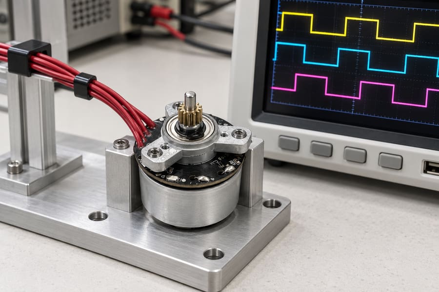
Illustrative traces show why simultaneous channels help compare transitions. They are not measured product data; acceptance requires recorded signals, an identified phase reference and documented operating conditions.
Practical verification should capture Hall A, Hall B, and Hall C simultaneously. Shared time references allow engineers to identify transition order, timing differences, and unexpected changes.
Where appropriate and safely measurable, capture relevant phase voltage, phase current, or back-EMF references alongside the Hall signals. These measurements support verification of electrical alignment.
State the exact waveform measurement location. Signals recorded at the motor connector may differ from those received at the controller because of harness loading or input conditioning.
Check signal levels against the documented output guarantees and receiver requirements. Oscilloscope observations should include sufficient voltage and timing resolution for the intended acceptance criteria.
The validation plan should cover representative supply conditions, startup, acceleration, steady rotation, deceleration, and direction changes where these behaviors are part of the application.
Testing at a single convenient speed cannot establish the complete timing envelope. Evaluate conditions that challenge transition frequency, signal quality, and the configured controller response.
For each test, retain the relevant motor configuration, pole-pair count, Hall bit order, direction viewpoint, phase identifiers, controller settings, and measurement conditions.
When reviewing the intended BLDC motor driver interface, verify that its supply, logic inputs, phase mapping, sampling, and filtering requirements match the documented motor characteristics.
Acceptance criteria should be established before testing. They may address permitted signal levels, transition order, timing deviation, recognized faults, and successful operation under representative loads.
Any modification to sensor wiring, controller filtering, phase mapping, or Hall alignment should trigger review of affected requirements. Previously approved traces may no longer represent the revised assembly.
Prepare the Final Electrical Interface Record
The approved interface package should include a controlled connector pinout, sensor electrical limits, pull-up ownership, receiver compatibility assessment, and documented supply and ground relationships.
It should also contain the actual Hall state sequence, rotation viewpoint, motor phase reference, pole-pair count, angular alignment information, and applicable controller timing settings.
Attach synchronized Hall and phase-reference waveform captures with test conditions, instrument references, observed deviations, application-defined acceptance criteria, and the responsible engineering approval.
The final deliverables are a revision-controlled electrical interface sheet, approved harness and phase-mapping drawings, validated controller configuration, and traceable startup, rotation, and fault-test records.