Inrunner brushless DC (BLDC) motors and permanent magnet synchronous motors (PMSMs) are used in applications that demand high rotational speeds, compact form factors, and precise torque control. They are widely applied in electric vehicles, drones, robotics, medical devices, industrial automation, and high-speed tools.
A critical design choice in any inrunner is winding configuration—the way copper coils are arranged in the stator slots. The two most common approaches are:
- Distributed winding (also called lap winding or distributed armature winding)
- Concentrated winding (also called tooth-coil winding)
Each winding style has significant implications on the motor’s efficiency, torque ripple, manufacturing complexity, and cost. The choice must be optimized based on the motor’s performance targets, size constraints, and application environment.
This article will explore:
- Basics of Inrunner Construction
- What is Distributed Winding?
- What is Concentrated Winding?
- Electromagnetic and Thermal Differences
- Impact on Performance Parameters
- Manufacturing and Cost Considerations
- Applications and Best Use Cases
- Comparison Table
- Selection Guidelines for Manufacturers
- Conclusion and Recommendations
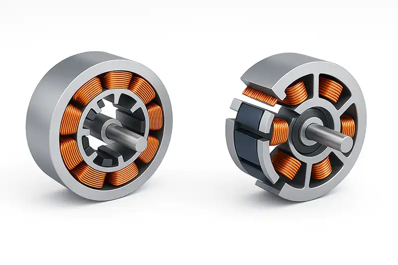
Inrunner Construction
Inrunner motors have the rotor inside and stator outside. The rotor is fitted with permanent magnets, while the stator holds laminated steel cores wrapped with copper windings. A minimal air gap between them enhances magnetic coupling.
Key features of inrunner designs:
- High-speed capability – better rotor stability and lower centrifugal stress compared to outrunners.
- Better cooling – stator windings are mounted on the outer frame, allowing easier heat dissipation.
- Compact form factor – especially beneficial for gear-driven or direct-drive high-RPM systems.
Why winding matters:
The winding type determines:
- How evenly the magnetic flux is distributed
- How much copper fits in the slots (slot fill factor)
- Torque smoothness and cogging torque
- Efficiency across different loads and speeds
What is Distributed Winding?
Distributed winding means that each phase winding is spread across multiple stator slots and spans several pole pitches. The coils are arranged so that their conductors are spread evenly around the stator’s circumference.
Key characteristics:
- Multiple slots per pole per phase (SPP): typically SPP > 1.
- Coil span (pitch) is usually 5/6, 2/3, or full pitch of the stator pole.
- Windings overlap with adjacent coils.
Advantages:
- Lower harmonic content in back-EMF → smoother torque.
- Lower torque ripple and minimized cogging torque
- More suitable for applications that demand minimal acoustic noise.
- Improved efficiency at high loads due to smoother current waveform.
Drawbacks:
- More complex winding process.
- Increased copper length per turn → higher resistance.
- Larger end-winding volume increases copper loss and motor length.
What is Concentrated Winding?
Concentrated winding means that each coil is wound around a single stator tooth without overlapping other coils. Each phase winding is concentrated in a small section of the stator.
Key characteristics:
- One slot per pole per phase (SPP ≈ 1) or fractional slot per pole per phase.
- Short end-windings and compact coil groups.
- Non-overlapping coil design.
Advantages:
- Shorter copper length → lower copper loss at light to medium loads.
- Quicker and simpler to produce, well-suited for automated manufacturing.
- Higher slot fill factor possible → more copper in the slot.
- More compact axial length.
Drawbacks:
- Higher harmonic distortion in back-EMF.
- Increased torque ripple and acoustic noise.
- May need skewing or fractional slot combinations to reduce cogging torque.
Electromagnetic and Thermal Differences
Electromagnetic impact
- Distributed winding produces a sinusoidal MMF (magnetomotive force) distribution, leading to low harmonic content.
- Concentrated winding produces a stepped MMF, leading to more space harmonics, which can increase losses in magnets and stator iron.
Thermal behavior
- Distributed windings often have longer end turns, increasing resistive heating.
- Concentrated windings have better thermal conductivity to the stator frame due to shorter end turns, but local hot spots can occur due to uneven heat distribution.
Magnetic Flux Illustration
- Distributed: Smooth sinusoidal flux density profile in air gap.
- Concentrated: More localized flux peaks, higher fundamental amplitude but higher harmonics.
Impact on Performance Parameters
| Parameter | Distributed Winding | Concentrated Winding |
| Torque ripple | Low | Higher (needs mitigation) |
| Cogging torque | Low | Higher without skew/fractional slots |
| Efficiency (low load) | Slightly lower due to end turns | Higher due to shorter copper length |
| Efficiency (high load) | Higher (low harmonics) | Slightly lower (core/magnet losses) |
| Power density | Moderate | Higher (shorter axial length) |
| Acoustic noise | Low | Higher without design measures |
| Cooling | Even but longer heat path | Short heat path, local hotspots |
Manufacturing and Cost Considerations
Distributed winding:
- Complex assembly due to overlapping coils.
- Often requires skilled manual winding or semi-automation.
- Higher copper usage → higher material cost.
- Ideal for low–medium volume, smooth torque production.
Concentrated winding:
- Simpler assembly, can be fully automated with preformed coils.
- Less copper required → lower material cost.
- Higher production throughput.
- Favored for mass production in cost-sensitive applications.
Applications and Best Use Cases
Distributed winding is ideal for:
- High-precision servo motors for CNC and robotics
- Traction motors for electric vehicles requiring smooth torque at all speeds.
- Aerospace and medical devices where low noise and vibration are essential.
- Industrial automation where dynamic performance outweighs cost.
Concentrated winding is ideal for:
- Small inrunner BLDC motors in drones and RC applications.
- High power density motors in e-bikes and electric scooters.
- Mass-produced fans and pumps where cost and size dominate.
- Compact gear-driven tools where short axial length is critical.
Detailed Comparison Table
| Feature / Factor | Distributed Winding | Concentrated Winding |
| MMF waveform | Smooth sinusoidal | Stepped, more harmonics |
| Copper usage | Higher | Lower |
| End-winding length | Long | Short |
| Core loss | Lower at high load | Higher due to harmonics |
| Magnet loss | Lower | Higher |
| Torque density | Moderate | High |
| Thermal management | Uniform heat spread | Better conduction, possible hotspots |
| Manufacturability | Complex | Simple |
| Production cost | Higher | Lower |
| Typical applications | Precision, low-noise, smooth-torque systems | High-volume, compact, cost-sensitive systems |
Selection Guidelines for Manufacturers
When selecting between distributed and concentrated windings for an inrunner design, consider:
Performance priorities
- Smooth torque → distributed.
- Compact size and high torque density → concentrated.
- Noise and vibration requirements
- Strict limits → distributed.
- Moderate tolerance → concentrated with skewed slots.
Production volume
- Low/medium → distributed.
- High volume → concentrated.
Operating speed range
- Wide range with high efficiency → distributed.
- Narrow range, high speed, compact → concentrated.
Thermal limits
- If cooling is challenging, concentrated winding’s short heat path may help.
- Material cost sensitivity
Concentrated winding reduces copper length and cost.
Both distributed and concentrated windings have strong use cases in inrunner designs, but they represent a trade-off between smoothness, efficiency, cost, and compactness.
Choose distributed winding when torque smoothness, low noise, and high efficiency under variable load are top priorities—common in precision servo drives, EV traction motors, and aerospace.
Choose concentrated winding when compact size, high torque density, and manufacturing efficiency matter most—ideal for e-bikes, drones, and mass-market appliances.
Manufacturers must also consider mitigation techniques:
For concentrated windings: use fractional-slot winding combinations, rotor skewing, and optimized magnet pole shaping to reduce cogging torque.
For distributed windings: design to minimize end-turn length for better efficiency.
Ultimately, the winding choice should be the result of a holistic motor design process, balancing electromagnetic design, mechanical constraints, cost targets, and production capabilities.