The Brushless DC Motor, commonly known as a BLDC motor, has revolutionized the way electrical energy is converted into motion. Unlike traditional brushed motors that rely on mechanical commutation, BLDC motors employ electronic control to achieve smoother operation, higher efficiency, and longer lifespan.
You’ll find BLDC motors in everything from electric vehicles (EVs) and drones to industrial automation systems and home appliances. Their unique combination of compact size, high torque-to-weight ratio, and precise controllability makes them the preferred choice for engineers seeking performance and reliability.
Basic Working Principle of BLDC Motors
At its core, a BLDC motor operates on electromagnetic principles. Current in stator windings creates magnetic force driving rotor rotation.
BLDC motors electronically energize coils, synchronizing with rotor motion. This process, known as electronic commutation, eliminates friction and wear associated with brushes, allowing higher speeds and lower maintenance.
The BLDC’s operation can be viewed as a synchronous motor system—the rotor follows the rotating magnetic field produced by the stator at the same frequency.
Anatomy of a BLDC Motor
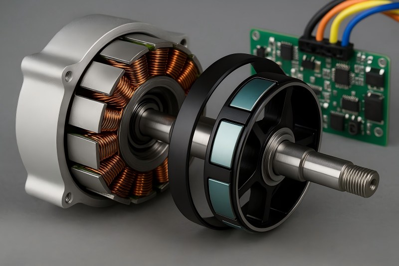
A BLDC motor’s structure is elegantly simple yet precisely engineered. It mainly consists of:
- Stator – the stationary part, carrying windings that generate the rotating magnetic field.
- Rotor – the rotating part, containing permanent magnets.
- Shaft – transmits mechanical output power.
- Sensors – Uses Hall sensors to detect rotor position.
- Controller (ESC) – handles power distribution and timing for the windings.
- Bearings & Housing – ensure smooth, quiet rotation and protection from environmental factors.
In general, BLDC motors are classified into two structural types: inner-rotor and outer-rotor. Inner-rotor designs are common in high-speed, low-torque applications, while outer-rotor motors are preferred for high-torque, compact systems such as drone motors.
The Stator: The Stationary Magnetic Field Generator
The stator is the powerhouse that creates the rotating magnetic field responsible for driving the rotor. Uses laminated steel sheets to minimize eddy loss and improve efficiency.These laminations are slotted to hold copper windings, which are energized in a sequence controlled by the electronic circuit.
Stator windings can be arranged in trapezoidal or sinusoidal configurations, depending on the control method used.
| Winding Type | Magnetic Field Shape | Control Type | Application Example |
| Trapezoidal | Trapezoidal back-EMF | 6-step commutation | Fans, pumps, simple drives |
| Sinusoidal | Smooth sine-wave back-EMF | Field-oriented control (FOC) | EVs, robotics, precision drives |
The core design of the stator directly influences torque ripple, noise level, and efficiency.
Modern BLDC stators are optimized using finite element analysis (FEA) to achieve minimal core loss and uniform magnetic flux.
Advanced manufacturing methods, such as laser cutting and progressive stamping, ensure tight tolerances and smooth lamination edges, which enhance insulation performance and reduce vibration.
Efficient cooling—via forced air, liquid cooling, or integrated heat sinks—is also critical, as stators handle continuous current flow, leading to potential heat buildup during operation.
The Rotor: The Rotating Magnetic Field Follower
The rotor’s magnets interact with the stator’s rotating field. Its design determines the motor’s torque density, inertia, and dynamic response.
Rotors can be classified by magnet placement:
Surface-Mounted Permanent Magnet (SPM) rotors have magnets placed on the outer surface of the rotor core. They’re simple and cost-effective, suitable for small motors and low-to-medium torque applications.
Interior Permanent Magnet (IPM) rotors embed magnets within the rotor core. They provide higher mechanical robustness, flux weakening capability, and efficiency at high speeds—ideal for EVs and industrial applications.
Impact of Pole Count
Increasing the number of magnetic poles enhances torque but reduces speed. Conversely, fewer poles allow higher RPMs but lower torque output. Engineers balance these parameters based on application requirements.
Mechanical Balance and Stability
The rotor is balanced to reduce high-speed vibration. Materials such as high-strength steel shafts and epoxy-bonded magnet holders ensure the rotor’s structural integrity under centrifugal forces.
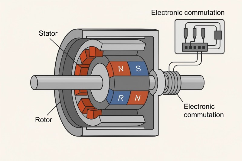
Electronic Commutation: The Heart of BLDC Control
One of the defining features of a BLDC motor is electronic commutation, which replaces mechanical brushes with semiconductor switches.
In brushed motors, brushes physically switch current direction as the rotor spins. In BLDC motors, sensors detect the rotor’s position, and the controller switches the current electronically, maintaining the correct phase sequence.
How Electronic Commutation Works
- Rotor Position Detection – Hall-effect sensors or sensorless algorithms determine the exact position of the rotor magnets.
- Signal Processing – The controller receives signals and decides which stator windings to energize.
- Switching Sequence – Transistors (often MOSFETs or IGBTs) switch on/off in a specific order to generate a rotating magnetic field.
- Feedback Control – Continuous monitoring ensures torque and speed stability.
This switching ensures smooth, fast, low-wear operation.
Hall Sensor vs. Sensorless Control
| Method | Advantages | Disadvantages |
| Hall Sensor-Based | Accurate low-speed control | Slightly higher cost and complexity |
| Sensorless Control | Cost-effective, robust | Poor startup at zero speed |
Modern controllers often integrate sensorless algorithms using back-EMF detection or observer-based estimations for compact, maintenance-free operation.
Control Techniques in BLDC Motors
Electronic control of BLDC motors can follow several strategies depending on application demands:
Six-Step (Trapezoidal) Control
The most common and straightforward approach, where current is switched through three phases in six discrete steps per electrical cycle.
- Pros: Simple, efficient, low cost.
- Cons: Produces torque ripple and higher acoustic noise.
Sinusoidal Control
Uses sinusoidal current waveforms to produce smoother torque output.
- Pros: Minimized vibration and noise levels.
- Cons: Reduced efficiency from higher switching losses.
Field-Oriented Control (FOC)
A sophisticated vector-control method that optimizes torque and flux independently.
- Pros: Precise speed and torque control, high efficiency.
- Cons: Requires complex processing and high-speed microcontrollers.
Comparison Table
| Control Type | Torque Smoothness | Efficiency | Complexity |
| Trapezoidal | Medium | High | Low |
| Sinusoidal | High | Medium | Medium |
| FOC | Very High | Very High | High |
Each technique finds its niche: trapezoidal control suits simple fan drives, while FOC dominates in EV and servo applications.
Performance Characteristics and Advantages
BLDC motors outperform brushed counterparts in nearly every aspect:
High Efficiency:
With no brush friction, BLDC motors achieve efficiencies exceeding 85–90%.
Low Maintenance:
No brushes mean reduced wear and fewer replacements, extending service life.
Compact and Lightweight:
High torque density allows smaller designs for the same output.
Precise Control:
Electronic commutation enables accurate speed and position control.
High-Speed Operation:
Capable of tens of thousands of revolutions per minute without arcing or brush wear.
Quiet Operation:
Minimizes vibration through smooth torque.
These features make BLDC motors the driving force behind next-generation electric and hybrid vehicles, robotic arms, HVAC systems, and medical instruments.
Common Challenges and Design Considerations
Despite their advantages, designing and operating BLDC motors involves certain engineering challenges:
Heat Management
Continuous current flow through stator windings generates heat. Designers must include proper cooling systems and thermal insulation to avoid demagnetization or insulation failure.
Demagnetization Risks
Excessive temperature or current spikes can weaken permanent magnets. Selection of high-coercivity rare-earth magnets (like NdFeB or SmCo) helps maintain long-term performance.
Cost and Complexity
BLDC systems require additional electronic components—controllers, sensors, and firmware—which increase cost and complexity compared to brushed motors.
Electromagnetic Interference (EMI)
High-speed switching in controllers may generate EMI, requiring proper filtering and shielding measures.
Calibration and Tuning
Precise alignment between sensors and magnetic poles is vital for smooth operation; misalignment can cause torque ripple or loss of synchronization.
Applications of BLDC Motors
The versatility of BLDC motors allows them to power a wide range of industries:
- Automotive: Electric power steering, fuel pumps, HVAC blowers, and traction motors in EVs.
- Industrial Automation: CNC machines, conveyors, robotic arms, and servomechanisms.
- Aerospace: Actuators, gyros, and compact drive systems requiring reliability under extreme conditions.
- Consumer Electronics: Cooling fans, hard drives, washing machines, and vacuum cleaners.
- Medical Devices: Ventilators, prosthetics, and laboratory centrifuges that demand quiet, precise control.
- Renewable Energy: Wind pitch and solar tracking systems.
BLDC technology continues to expand into new domains—especially micromotors for drones and precision actuators for automation.
The Brushless DC Motor exemplifies modern engineering efficiency—uniting magnetic precision, smart electronics, and mechanical simplicity. Its stator produces rotating fields with minimal losses, the rotor converts magnetic flux into torque, and electronic commutation ensures synchronized, spark-free control.
As industries demand cleaner energy and smarter motion systems, BLDC motors will continue leading innovation. With advancements in sensorless algorithms, high-temperature magnets, and integrated motor controllers, the next generation of BLDC motors will be even more compact, intelligent, and powerful.
Whether driving an electric car, a surgical robot, or a factory conveyor, the BLDC motor stands as a perfect fusion of physics and digital control—an elegant machine built for the future.