Inrunner brushless DC (BLDC) motors are widely used in industries ranging from electric vehicles and drones to medical devices, robotics, and high-speed power tools. Their compact cylindrical configuration, where the rotor spins inside the stator, offers advantages in high-speed stability, efficient cooling, and precise torque control.
One of the most critical elements influencing the performance of inrunner BLDC motors is the stator lamination—the stack of thin steel sheets forming the stator core. This component directly impacts magnetic efficiency, core losses, heat dissipation, manufacturing cost, and overall motor performance.
Choosing the right stator lamination type, material, thickness, and manufacturing process is essential for achieving the optimal balance between efficiency, power density, and cost.
Stator Laminations in Inrunner BLDC Motors
The stator of an inrunner BLDC motor is made from stacked laminations of electrical steel, rather than being a single solid piece. Laminated construction reduces eddy current losses caused by alternating magnetic fields in conductive motor materials.
Functions of Stator Laminations
- Magnetic Flux Conduction: Guide and concentrate magnetic flux between rotor magnets and windings.
- Loss Reduction: Minimize eddy current and hysteresis losses compared to a solid core.
- Thermal Management: Help dissipate heat generated in the windings and core.
- Structural Support: Provide a rigid base for winding placement and rotor clearance.
For inrunner motors, laminations are typically formed into slotted designs that hold distributed or concentrated windings. The number of slots, their shape, and the lamination thickness all influence electromagnetic behavior.
Materials Used in Stator Laminations
The choice of lamination material affects magnetic permeability, saturation levels, resistivity, and losses. Common materials include:
Silicon Steel (Electrical Steel)
Composition: Iron alloyed with 2–3.5% silicon.
Advantages: High electrical resistivity, reduced eddy currents, good magnetic permeability.
Grain Orientation:
- Non-Grain-Oriented (NGO): Isotropic magnetic properties; common in rotating machines.
- Grain-Oriented (GO): Optimized for one magnetic direction; rarely used in rotating stators.
Use Case: Most common choice for inrunner BLDC stators.
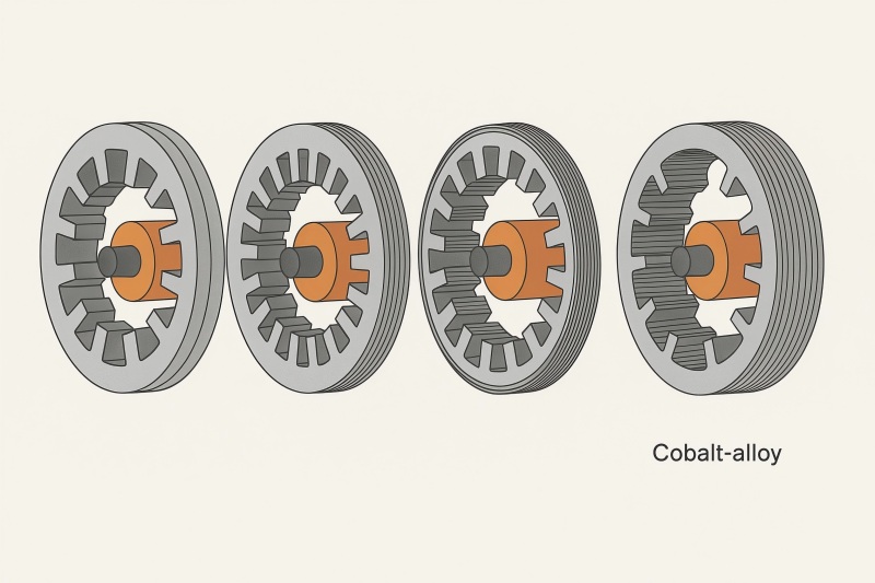
Cobalt-Iron Alloys
- Advantages: Higher saturation flux density (~2.35 T), good high-frequency performance.
- Drawbacks: Expensive, harder to machine.
- Use Case: Aerospace motors, high-speed spindles, and power-critical density applications.
Nickel-Iron Alloys
- Advantages: High permeability, low hysteresis loss.
- Drawbacks: Lower saturation level than cobalt alloys, higher cost than silicon steel.
- Use Case: Specialty applications like precision instrumentation.
Lamination Thickness Options and Their Effects
The thickness of each lamination sheet directly impacts eddy current losses, manufacturing cost, and mechanical robustness.
| Thickness | Eddy Current Losses | Mechanical Strength | Cost | Typical Application |
| 0.50 mm | Higher | High | Low | Low-speed motors |
| 0.35 mm | Moderate | Good | Medium | Standard BLDC motors |
| 0.20–0.27 mm | Low | Lower | Higher | High-speed inrunners |
| 0.10 mm | Very low | Fragile | Very High | Aerospace/high-frequency |
Trade-off: Thinner laminations reduce eddy current losses but increase cost and complexity.
Manufacturing Techniques for Stator Laminations
Stamping
- Process: Progressive dies punch shapes from steel sheets.
- Advantages: High-volume efficiency, repeatability.
- Limitations: Tooling cost, burr formation, not ideal for ultra-thin sheets.
Laser Cutting
- Advantages: No expensive tooling, flexible design changes.
- Limitations: Lower throughput, potential heat-affected zones.
- Use Case: Prototyping and low-volume runs.
Wire EDM (Electrical Discharge Machining)
- Advantages: Very high precision, smooth edges.
- Limitations: Very slow, high cost.
- Use Case: Special-purpose motors requiring tight tolerances.
Bonded Laminations
- Laminations glued or bonded rather than mechanically stacked.
- Advantage: Reduced vibration noise and improved thermal paths.
- Drawback: Added manufacturing complexity.
Insulation Coatings and Treatments
Electrical insulation coatings are applied to each lamination to prevent interlaminar currents.
Common Coating Classes
- Class C-2 (Organic Inorganic Hybrid): Good thermal resistance, suitable for high-speed motors.
- Class C-3 (Inorganic): High temperature stability, less flexibility.
- Class C-5 (Thin Organic Film): Minimal thickness for better stacking factor.
Coating choice affects stacking factor, heat dissipation, and core loss.
Performance Trade-offs of Different Lamination Choices
Key factors influenced by lamination selection:
- Efficiency: Thinner, higher-quality laminations reduce core losses.
- Torque Ripple: Slot shape and lamination design impact cogging torque.
- Thermal Performance: Better materials and coatings aid heat dissipation.
- Noise and Vibration: Bonded laminations can dampen mechanical noise.
- Cost: Influenced by material grade, thickness, and manufacturing method.
Application-Specific Considerations
Electric Vehicles
- Priority: Efficiency, thermal stability, high power density.
- Lamination Choice: 0.27–0.35 mm NGO silicon steel with Class C-2 coating.
Drones and UAVs
- Priority: Lightweight, high-speed capability.
- Lamination Choice: 0.20 mm cobalt alloy for ultra-low losses.
Industrial Automation
- Priority: Long life, reliability, cost balance.
- Lamination Choice: 0.35 mm NGO silicon steel, bonded stack.
Medical Devices
- Priority: Low noise, precision torque.
- Lamination Choice: Bonded, thin laminations with smooth EDM or laser edges.
Cost and Supply Chain Factors
- Raw Material Price: Cobalt alloys can cost 3–5× more than silicon steel.
- Tooling Investment: Stamping requires high initial die costs.
- Volume Needs: High-volume production benefits from stamping; low volume favors laser cutting.
- Lead Times: Custom laminations may require weeks to months for material procurement.
Comparison Table
| Factor | Thick NGO Steel (0.50 mm) | Standard NGO Steel (0.35 mm) | Thin NGO Steel (0.20 mm) | Cobalt Alloy (0.20 mm) |
| Losses | High | Medium | Low | Very Low |
| Cost | Low | Medium | High | Very High |
| Strength | High | High | Medium | Medium |
| Frequency | Low-speed | Mid-speed | High-speed | Very high-speed |
| Efficiency | Low | Good | Very Good | Excellent |
Selection Guidelines for Manufacturers
When choosing stator laminations for inrunner BLDC motors, consider:
Target Speed and Efficiency:
For <10,000 RPM: 0.35–0.50 mm silicon steel.
For >30,000 RPM: ≤0.20 mm laminations.
Cost Constraints:
Use standard NGO silicon steel for most cost-sensitive markets.
Reserve cobalt alloys for high-margin, high-performance applications.
Thermal Requirements:
Use coatings with high thermal conductivity and stability.
Noise/Vibration Targets:
Consider bonded laminations or skewed slots for quieter operation.
Production Volume:
High volume → stamping; low volume → laser cutting.
Stator lamination choice is a critical design decision for inrunner BLDC motors, influencing efficiency, cost, weight, and application suitability.
For mainstream applications such as industrial automation and electric scooters, 0.35 mm NGO silicon steel remains the optimal choice, offering a balance between cost and performance.
For high-speed or high-efficiency applications such as aerospace, drones, or medical precision tools, thinner laminations (≤0.20 mm) with premium coatings deliver measurable gains, albeit at higher cost.
Manufacturers should collaborate closely with lamination suppliers, considering not only electromagnetic performance but also manufacturability, coating choice, and supply chain stability. In a competitive market where efficiency and performance margins matter, the right stator lamination choice can mean the difference between a good motor and an exceptional one.