Gear motors are a cornerstone of modern motion systems, combining an electric motor and a gearbox into a compact, efficient unit. Gear ratio is key to the system’s overall performance. Whether powering robotics, conveyor belts, medical devices, or industrial automation, understanding how gear ratios impact speed and torque is essential for selecting the right gear motor for any application.
What Is a Gear Ratio?
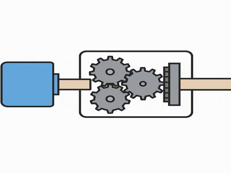
In a gear motor system, the relationship between the input and output gears determines the gear ratio, which in turn determines how speed and torque are transformed.
Formula:
Gear Ratio=Number of Teeth on Output Gear/Number of Teeth on Input Gear
Alternatively, for gear motors:
Gear Ratio=Input Speed (Motor RPM)/Output Speed(Gearbox RPM)
Example:
If the motor spins at 3000 RPM, gearbox output shaft rotates at 100 RPM, the gear ratio is:
3000/100=30:1
Gear Ratios’ Impact on Speed and Torque
The primary role of gear ratios is to convert speed to torque or vice versa. In gear motors, this transformation is critical to meet the mechanical needs of different applications.
| Gear Ratio Type | Speed Change | Torque Change | Application Example |
| High Ratio (e.g. 100:1) | Drastically reduced output speed | Greatly increased torque | Lifting equipment, conveyors |
| Low Ratio (e.g. 5:1) | Slightly reduced output speed | Slightly increased torque | Robotics, fans, pumps |
| 1:1 Ratio | No change | No change | Direct drive systems |
Key Effects:
Higher Gear Ratios = Lower speed, higher torque
Lower Gear Ratios = Higher speed, lower torque
This relationship is inversely proportional—increasing one reduces the other.
Torque-Speed Trade-Off Explained
Gear motors obey the principle of conservation of power, minus mechanical losses. If a motor produces a certain amount of power (P), then:
P=Torque×Angular Velocity
If speed (angular velocity) is reduced through a gearbox, the torque must increase, assuming constant power (and ignoring losses).
Torque Gain Formula:
Output Torque=Motor Torque×Gear Ratio×Efficiency
Efficiency Factor:
Gearboxes are not 100% efficient. Typical efficiencies range from:
- Spur gears: 95–98%
- Planetary gears: 90–95%
- Worm gears: 70–90%

Types of Gearboxes and Their Ratios
Spur Gearbox
- Simple design, easy to manufacture
- Used in low-speed, low-torque applications
- Gear ratios: 1:1 to 12:1 typically
Planetary Gearbox
- High torque density
- Compact size
- Ratios: 3:1 to 100:1+
Worm Gearbox
- High ratios in a single stage (up to 100:1)
- Self-locking capability
- Lower efficiency due to sliding contact
Selecting the Right Gear Ratio
When choosing a gear motor, selecting the proper gear ratio is crucial for ensuring the motor:
- Operates within desired speed and torque
- Avoids overheating or stalling
- Matches the load requirements
Practical Considerations:
- Load Torque Requirement: Calculate how much torque your application needs.
- Motor Torque: Make sure the motor delivers sufficient torque, accounting for gear ratio and efficiency losses.
- Speed Requirement: Choose a ratio that brings motor RPM down to target RPM.
- Duty Cycle: For continuous use, prioritize thermal management.
Real-World Examples
Let’s illustrate the relationship between gear ratio, speed, and torque through examples.
Example 1: Conveyor System
| Specification | Value |
| Motor Speed | 3000 RPM |
| Required Belt Speed | 100 RPM |
| Load Torque Requirement | 10 Nm |
| Gearbox Efficiency | 90% |
Step 1: Calculate Required Gear Ratio
Gear Ratio=3000/100=30:1
Step 2: Calculate Motor Torque
- Motor Torque=10 Nm/30×0.9=0.37 Nm
- Thus, a motor with at least 0.4 Nm torque and a 30:1 gearbox can drive the system.
Common Gear Ratios and Their Applications
| Gear Ratio | Output Speed (If Motor = 3000 RPM) | Torque Gain | Typical Application |
| 5:1 | 600 RPM | 5× | Small pumps, fans |
| 10:1 | 300 RPM | 10× | Light-duty conveyor belts |
| 30:1 | 100 RPM | 30× | Packaging machines |
| 60:1 | 50 RPM | 60× | Lifting platforms |
| 100:1 | 30 RPM | 100× | Heavy industrial actuators |
Calculating Output Parameters
When given a motor and gear ratio, you can determine output torque and speed using:
Output Speed=Motor Speed/Gear Ratio
Output Torque=Motor Torque×Gear Ratio×Efficiency
Example Table:
| Motor Torque (Nm) | Gear Ratio | Efficiency | Output Torque (Nm) |
| 0.5 | 10:1 | 95% | 4.75 |
| 0.5 | 20:1 | 90% | 9.00 |
| 0.5 | 50:1 | 85% | 21.25 |
When Gear Ratio Goes Wrong
Incorrect gear selection can lead to:
- Over-speeding: Insufficient torque, risk of stalling
- Over-torqueing: Overstressing mechanical parts
- Heat Buildup: Inefficient power transfer
- System Instability: Oscillations in precise control systems
To avoid these issues:
- Always calculate torque margin
- Consult motor curves and gearbox ratings
- Factor in inertia and load variation
Tips for Gear Ratio Optimization
- Start With Load Requirements: Speed and torque demands define your motor-gearbox choice.
- Avoid Over-Gearing: High gear ratios reduce speed too much and increase system size.
- Consider Backlash: High-ratio gearboxes may introduce play—critical for precision tasks.
- Include Safety Margin: Add 20–30% to torque requirements for real-world conditions.
- Test Under Load: Simulate actual conditions to ensure the gear motor performs reliably.
Gear ratios are at the core of gear motor performance. They directly influence how motor power is delivered—by reducing speed to increase torque or vice versa. Choosing the correct ratio ensures that your gear motor meets application demands efficiently, reliably, and safely.
As a gear motor manufacturer, we offer customizable gear ratios to match your specific speed and torque requirements. Our engineering team can assist in selecting or designing gear motors that optimize your system performance while maximizing energy efficiency and longevity.
Whether you’re automating production lines or designing precision robotics, understanding gear ratios empowers smarter decisions that drive your projects forward.