
Resistance measurements can estimate the average copper winding temperature of an inrunner BLDC motor by comparing its hot resistance with a value recorded at a known reference temperature.
The result describes the resistance-weighted average conductor temperature along the measured winding path, not a local hotspot or rotor-magnet temperature. Reliable estimates require consistent connections, controlled test current, and careful timing.
What Does Resistance-Based Winding Temperature Estimation Actually Measure?
For custom inrunner BLDC motor windings, resistance-based temperature estimation can support evaluation when the measurement method and thermal acceptance criteria are defined for the actual winding.
Related brushless DC motor configurations may use different winding connections, so the terminal convention must be documented rather than assumed.
Relationship Between Copper Resistance and Temperature
Copper resistance changes with temperature because the movement of charge carriers is increasingly affected by lattice vibrations as the conductor becomes warmer. For ordinary motor-winding temperature ranges, this behavior is commonly approximated with a linear resistance-temperature relationship.
When the winding heats during operation, its electrical resistance generally rises. Comparing that resistance with a cold reference therefore provides an indirect estimate of the conductor temperature change.
The winding itself serves as the temperature-sensitive element, provided its material and electrical path are understood.
Average Winding Temperature vs. Local Hotspot Temperature
The calculated value represents a resistance-weighted average temperature of the conductors contributing to the measured path. It is not a map of temperature across the stator, nor does it identify the hottest point.
Turns, slot sections, end windings, and connections can differ in temperature because their cooling and local losses vary. A small hot region may contribute relatively little to total resistance.
Consequently, a resistance-derived average can remain below a specified hotspot limit even when a localized area is warmer. The calculation alone cannot prove that every part of the winding remains below that limit.
Report the resistance result as “estimated average conductor temperature.” Reserve “hotspot temperature” for a suitable local measurement or validated thermal method.
Winding Temperature vs. Rotor-Magnet Temperature
The stator winding and rotor magnets occupy different locations and follow different heat-transfer paths. Their temperatures depend on separate losses, thermal resistances, airflow, interfaces, and operating conditions.
Winding resistance therefore cannot directly determine the temperature of permanent magnets inside the rotor. Magnet temperature requires separate sensing or an independently validated thermal assessment using relevant rotor and motor data.
Do not apply the calculated winding temperature to a magnet-temperature limit or describe it as a rotor temperature. The two values may differ substantially during transient operation.
Establish a Reliable Cold Reference and Measurement Configuration
Stabilize the Winding at a Known Reference Temperature
A useful calculation starts with a reference resistance measured when the winding temperature is known and stable. If the motor has just been transported, operated, or stored in changing conditions, allow its winding to settle before testing.
Record the reference temperature in degrees Celsius and identify how it was established. A nearby room-temperature reading is not automatically the winding temperature, particularly when the motor has a different thermal history.
Use a suitable sensor to represent winding temperature, or document the controlled soak conditions used to establish thermal stability.
Do not begin the reference measurement while the motor is still warming or cooling. A changing reference temperature introduces uncertainty before the hot measurement is even taken.
Measure Reference Resistance Using a Four-Wire Kelvin Method
Inrunner motor windings can have low resistance, making ordinary two-wire measurements vulnerable to test-lead and contact resistance. These unwanted resistances can be significant compared with the winding value being measured.
A four-wire Kelvin arrangement uses one pair of leads to carry the test current and a separate pair to sense voltage directly at the measurement points.
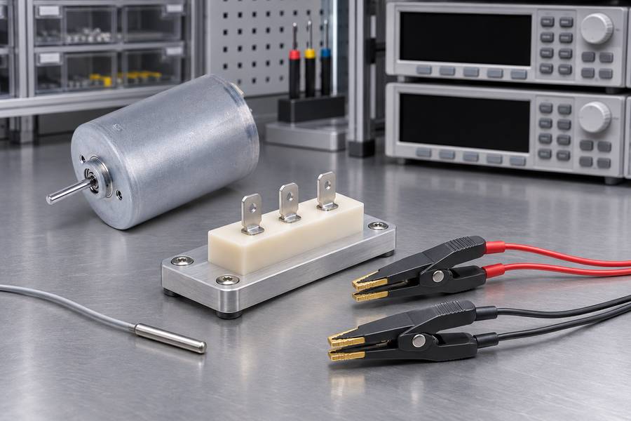
Because the voltage-sensing circuit draws very little current, lead voltage drops have much less influence on the calculated resistance.
Connect the current and sense leads according to the instrument instructions, and place the sense contacts as close as practical to the defined winding terminals. Keep the contact locations consistent between reference and hot readings.
Four-wire measurement reduces lead and contact effects but cannot eliminate errors from oxidized terminals, unstable clips, poor probe placement, or changing contact pressure.
Record the measured reference resistance in ohms, the terminal pair, the instrument range, and the test current. Retaining these details makes a later comparison reproducible.
Keep Measurement Terminals and Test Conditions Consistent
The cold and hot measurements must represent the same electrical path. Measuring one phase at the reference stage and a different terminal pair after operation can create a misleading resistance ratio.
Keep the winding connection unchanged, whether the measurement is made across a defined phase winding or between motor terminals. Record the exact terminals and whether the result is phase resistance or line-to-line resistance.
Use a test current low enough to avoid appreciable self-heating during the measurement. A winding with low thermal mass can begin warming if current is applied for too long, especially when resistance is measured repeatedly.
Use the same instrument method, current, connection points, and contact procedure for both readings. Document any unavoidable change and assess its effect.
| Reference item | What to establish and record |
| Winding condition | Stable temperature and the method used to establish it |
| Reference temperature | Measured or justified winding temperature in °C |
| Resistance path | Exact terminals, phase or line-to-line convention, and connection topology |
| Measurement method | Four-wire Kelvin arrangement, instrument range, and test current |
| Reference resistance | Raw resistance reading in Ω, including repeat measurements |
Measure Hot Winding Resistance After Motor Operation
Isolate the Motor Before Resistance Measurement
After the operating condition has been completed, stop the motor and isolate its winding from the drive and other energized circuits. Follow the applicable electrical safety procedure before connecting test equipment.
Verify that the measurement points are de-energized and that the drive cannot apply voltage during the resistance test. An ordinary ohmmeter must never be connected to an energized motor or drive circuit.
Separate parallel paths or external components if they would affect the result. Measure the intended winding path, not an unintended combination of winding and drive circuitry.
Obtain Repeatable Hot Resistance Readings
Measure hot resistance with the same four-wire setup used for the cold reference. Use the same terminal pair, contact locations, connection convention, and suitably low test current.
Record the first valid reading and its time after shutdown. Take additional readings when practical, noting the time of each measurement rather than recording an undated group of values.
Repeated readings can reveal unstable contacts or probe placement. If values vary, inspect the connections before calculating a representative winding resistance.
More readings do not automatically improve accuracy: test current can add heat, while elapsed time allows cooling. Control the sequence and timing.
Account for Stop-to-Read Delay and Winding Cooling
Winding temperature begins to fall after shutdown as heat moves into the stator core, housing, rotor, and surrounding air. Copper resistance falls with that temperature, so a delayed reading is usually lower than the shutdown-time resistance.
Record the interval between stopping the motor and obtaining each reading. A result measured after a long delay should not be presented as the resistance at the instant the motor stopped.
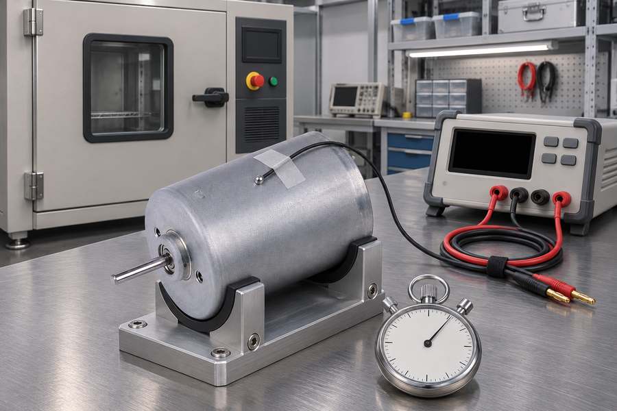
If immediate measurement is impractical, collect several readings at documented intervals and examine the resistance trend. The trend can support an estimate of the earlier resistance, but the extrapolation method and its assumptions must be stated.
A simple trend may help over a short interval when readings are stable, but one delayed reading cannot establish shutdown-time resistance.
Do not extrapolate beyond the data or treat a fitted curve as the internal temperature distribution. The estimate still depends on timing, repeatability, and model suitability.
Keep measured and estimated values separate in the report. Label the directly observed value “resistance at [recorded delay]” and identify any corrected value as an “estimated shutdown-time resistance.”
Calculate Average Winding Temperature Using Copper Resistance
Apply the Copper Resistance-Temperature Formula
For a copper winding, a commonly used approximation relates hot resistance to resistance at a known reference temperature. With temperatures expressed in degrees Celsius, the calculation is:
Thot = (Rhot / Rref) × (Tref + 234.5) − 234.5
Here, Thot is the estimated average hot conductor temperature in °C; Rhot is hot resistance in ohms; Rref is reference resistance in ohms; and Tref is the known reference temperature in °C.
The value 234.5°C is a typical temperature constant used for annealed copper. It is an engineering approximation, not a universal material constant that should be assigned to every conductor without checking.
Actual conductor composition, condition, and manufacturing details can affect the resistance-temperature relationship. If the conductor supplier’s data or a validated material-specific calibration is available, use that information instead of assuming the typical constant.
The equation assumes resistance changes primarily reflect conductor temperature; it cannot correct changed terminals, contact resistance, parallel paths, or altered connections.
Work Through a Hypothetical Inrunner Motor Calculation
The following example is illustrative only. It is not a measured motor result, a Gian Transmission product specification, or a recommended operating limit.
| Measurement parameter | Illustrative value |
| Reference temperature, Tref | 20°C |
| Reference resistance, Rref | 0.500 Ω |
| Hot resistance, Rhot | 0.650 Ω |
| Resistance ratio | 1.300 |
| Assumed copper constant | 234.5°C |
First, divide the hot resistance by the reference resistance: 0.650 Ω / 0.500 Ω = 1.300. The ratio is dimensionless because both measurements use ohms.
Next, substitute the ratio and reference temperature into the equation: Thot = 1.300 × (20 + 234.5) − 234.5.
The calculation gives 1.300 × 254.5 − 234.5 = 330.85 − 234.5 = 96.35°C. The estimated average conductor temperature is therefore approximately 96.4°C.
This value describes the average conductor temperature represented by the measured path, subject to the stated assumptions. It does not establish a local winding hotspot, rotor-magnet temperature, or compliance with a product-specific thermal limit.
Identify Conditions That Can Invalidate the Calculation
A mathematically correct formula can still produce an unreliable result when its inputs do not represent comparable winding conditions. Check the measurement process before interpreting the calculated temperature.
- Reference instability: The winding was not at a known, stable temperature when Rref was recorded.
- Different resistance path: The terminal pair, phase path, or winding connection changed between measurements.
- Lead and contact effects: Two-wire resistance, poor contacts, or inconsistent probe positions materially affected either reading.
- Measurement self-heating: Test current or measurement duration warmed the winding during resistance acquisition.
- Material mismatch: The assumed copper constant does not adequately represent the actual conductor.
- Unrecorded cooling: The hot reading was delayed, but the shutdown-to-read interval was ignored.
Account for Winding Topology and Phase Resistance Differences
Understand Phase Resistance and Line-to-Line Resistance
A phase-resistance measurement and a line-to-line measurement are not interchangeable descriptions. The relationship between them depends on how the winding phases are connected and which terminals are accessible.
In a star-connected winding, a line-to-line measurement typically includes two phase windings in series when the neutral point is inaccessible and the phases are otherwise comparable.
In a delta connection, the measured path includes a combination of one phase branch and the parallel path through the other two branches.
Thus, line-to-line resistance differs from individual phase resistance; identify the topology and measurement convention before interpreting it.
Understand When the Resistance Ratio Can Be Used
If both cold and hot measurements use the same terminal pair and unchanged topology, a stable topology-related factor can cancel in the resistance ratio.
This can make a line-to-line ratio useful without converting every reading into phase resistance first.
That cancellation depends on comparable phase temperatures and a consistent electrical path. It should not be assumed when the phases heat unevenly, a connection changes, or the measurement includes different external paths.
Do not apply a universal star-to-delta conversion factor to readings taken under different configurations. A conversion may be appropriate for a defined circuit model, but it is not a substitute for documenting the actual winding arrangement.
Identify Unequal Phase Temperatures
Unequal phase temperatures can influence line-to-line resistance because each measurement may combine more than one phase contribution. The resulting value may not represent any single phase’s average temperature.
Causes include uneven airflow, cooling differences, winding asymmetry, and unequal loading. Phase-level assessment must account for these conditions.
A single line-to-line resistance measurement cannot independently determine all three phase temperatures. Where imbalance matters, define a suitable set of phase measurements or use another validated method that can distinguish the individual winding conditions.
Evaluate Measurement Uncertainty and Define Thermal Acceptance Requirements
Identify the Main Sources of Measurement Uncertainty
The final temperature estimate depends on the accuracy of both resistance readings and the reference temperature. Small errors can matter when the winding resistance is low or the measured resistance increase is modest.
Four-wire measurement reduces lead-resistance effects, but contact conditions, instrument limits, test current, duration, and connection repeatability still matter.
Cooling delay adds another uncertainty when the objective is to estimate shutdown-time temperature. The uncertainty depends on the timing accuracy, number of readings, resistance trend, and assumptions used for extrapolation.
The material constant introduces model uncertainty if the actual conductor relationship is not known. Phase imbalance can add another limitation when a line-to-line result is interpreted as though every phase had the same temperature.
Evaluate Repeatability and Temperature Estimation Confidence
Repeatability should be assessed using repeated measurements made with the same setup and timing. A stable series supports confidence in the resistance value, while unexplained variation calls for connection checks or a revised measurement procedure.
Do not hide variation by reporting only a rounded average. Preserve individual readings, calculate a representative value using a defined method, and report the spread or measurement uncertainty separately.
Temperature uncertainty should reflect uncertainty in resistance and reference temperature, along with material and timing assumptions where they are significant. Do not report a temperature to hundredths of a degree when the measurement process cannot support that precision.
When results are close to an acceptance boundary, uncertainty becomes important to the decision. The acceptance procedure should state how the uncertainty is treated rather than silently comparing a rounded estimate with a limit.
Compare Estimated Temperature Against the Specified Winding Limit
Establish the applicable winding or insulation-system temperature requirement before evaluating the result. The limit must be defined for the actual motor design and intended operating conditions, not borrowed from an unrelated motor.
Distinguish an average winding-temperature criterion from a maximum hotspot requirement. A resistance-derived average can be useful for thermal evaluation, but it cannot independently demonstrate that a local hotspot remains below its limit.
An insulation thermal-class designation should not automatically be treated as the permissible operating temperature of the complete motor. The motor’s allowable temperature depends on its insulation system, construction, materials, duty, and specified design limits.
Do not invent a universal acceptable winding temperature or infer a product limit from the copper equation. If the required limit has not been specified, the thermal acceptance decision remains incomplete.
Define Procurement Documentation and Verification Records
Define the measurement method in the procurement specification before testing, so both parties use the same terminal convention, reference condition, and temperature interpretation.
Require the report to identify the motor and winding configuration, conductor material if known, reference temperature, reference resistance, hot resistance, and the terminals used for both measurements.
Also record the four-wire arrangement, instrument information, test current, raw repeated readings, motor operating condition, shutdown time, and each resistance measurement time. If a shutdown-time value is extrapolated, include the method and supporting readings.
The report should state the temperature constant or material-specific calibration used, show the calculation, and identify the result as an average conductor temperature. Include measurement uncertainty and distinguish measured values from estimates.
Finally, define the acceptance criterion in advance: identify whether it applies to average winding temperature or a local hotspot, state the applicable limit and uncertainty rule, and specify what happens when results are inconclusive or exceed the requirement.
For custom inrunner winding projects, Gian Transmission’s winding configuration and the buyer’s thermal requirements should be addressed through project-specific documentation. Do not assume a universal thermal limit or embedded temperature sensor unless the agreed design explicitly includes it.