
An inrunner BLDC pump motor needs a shaft-seal interface defined around the pump’s fluid boundary, shaft geometry, and operating conditions. Motor dimensions alone cannot establish leakage control or process compatibility.
Buyers should identify who supplies and validates the seal, which interface data the motor supplier must control, and how the assembled arrangement will be inspected before release.
Where Is the Sealing Boundary, Which Seal Type Is Required, and Who Supplies It?
For projects requiring a purpose-built rotor and shaft arrangement, review Gian Transmission’s custom inrunner BLDC motor solutions. The broader brushless DC motor range provides additional context for defining the motor platform.
Identify the Actual Sealing Boundary
Start with a section drawing of the complete motor-pump assembly. Mark the fluid chamber, rotating shaft, bearings, housing joints, and electrical compartments.
Identify where process fluid is permitted and where it must be stopped. The seal may separate the pump chamber from a bearing cavity, motor interior, or intermediate drain space.
Check other possible paths too, including housing joints, fastener passages, cable entries, and the pump-to-motor mounting interface.
The boundary drawing should show which side is normally wet, which side is expected to remain dry, and whether an intermediate space is intentionally allowed to collect leakage.
This prevents the word “sealed” from hiding different expectations among the motor and pump teams.
Distinguish the Sealing Mechanisms
A radial lip seal uses a flexible lip against the cylindrical shaft surface. Performance depends on the shaft track, lubrication, pressure direction, temperature, and permitted movement.
A mechanical face seal controls leakage across mating faces arranged generally perpendicular to the shaft axis. Face materials, axial loading, and chamber geometry therefore require separate consideration.
These mechanisms are not interchangeable. Static seals, such as gaskets or O-rings at housing joints, seal stationary interfaces rather than rotating shaft penetrations.
When comparing options, describe the actual sealing duty rather than specifying only a generic “shaft seal.” The required leakage control, available axial space, shaft surface, and lubrication arrangement help determine which mechanism is appropriate.
Separate Bearing Protection from Process Containment
A bearing seal commonly retains lubricant and limits dirt or moisture around a bearing. That function does not prove that it can contain process fluid.
Confirm whether the bearing is exposed to the pump fluid, whether a separate process seal is needed, and where leakage travels if the primary seal fails.
Assign Design and Supply Responsibilities
Record who selects, supplies, installs, and replaces the seal. The pump designer may own the process seal, while the motor supplier defines the shaft and mounting interfaces.
Gian Transmission offers custom shaft and mounting interfaces; this does not imply an included pump-fluid seal, wet-running certification, or particular ingress rating.
Document responsibility for seal selection, chamber design, shaft dimensions, installation, leakage acceptance, and final assembly approval.
Also identify who approves deviations when the selected seal requires a shaft feature or chamber dimension that differs from the preliminary motor drawing. Resolve those differences before tooling or production dimensions are released.
What Shaft Dimensions and Surface Characteristics Does the Selected Seal Require?
Define the Shaft Diameter and Sealing Track
Specify the nominal diameter at the actual sealing track. Show its axial position, usable width, and relationship to shoulders, steps, keyways, and threads.
State the dimensional tolerance and controlling datum. The selected seal’s requirements should determine the tolerance; no universal value suits every design.
Identify which shaft surface contacts the seal and which features guide assembly. An overall shaft diameter alone is insufficient for machining and inspection.
Where a shoulder locates the seal or a sleeve forms the running surface, dimension that feature from the same functional datum.
If a replaceable sleeve is used, define its retention, finished diameter, and replacement inspection separately from the motor shaft.
Control Geometry and Runout
Radial runout at the seal track describes shaft-surface movement relative to the seal during rotation. Excessive variation can alter contact, accelerate wear, or create a leakage path.
Define the measurement datum, indicator location, support condition, and whether inspection applies to the bare shaft or assembled rotor. Specify roundness, cylindricity, or concentricity separately where required.
Do not compare readings taken with different support arrangements as though they represent the same condition. If the shaft is inspected between centers, on bearing journals, or in the assembled motor, state that setup on the inspection plan.
Specify Surface Finish and Machining Lead
Surface roughness must suit the selected seal and operating conditions. Excessive roughness can accelerate wear, while unsuitable texture can interfere with stable contact.
Check machining direction as well. A helical tool path can encourage fluid to travel along the shaft, so specify the required texture and inspection direction.
Use the roughness parameter and acceptance method defined for the seal. Do not insert a generic Ra value without confirming the application requirement.
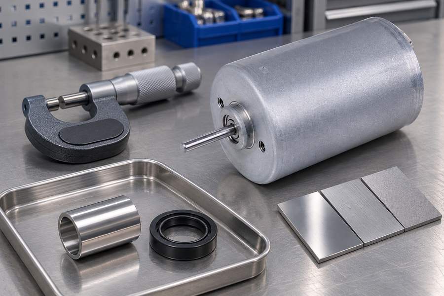
Inspect the actual contact track rather than a nearby machined face. A report should identify the measurement location and direction, because a single reading away from the seal path may not represent the running surface.
Check Hardness and Surface Treatments
Surface hardness affects wear resistance, but any hardening or coating requirement depends on the shaft, seal, fluid, contact conditions, and maintenance plan.
For a coating, account for thickness and finished diameter. Verify adhesion, continuity, final finish, and fluid compatibility; inspect the completed sealing track after all treatments.
| Interface item | What the drawing or specification should identify | Inspection focus |
| Sealing diameter | Nominal size, tolerance, axial location, and datum | Measure the defined track at the specified locations |
| Runout and form | Applicable geometric controls and measurement setup | Use the stated datum and shaft support condition |
| Surface condition | Roughness, texture, machining lead, and evaluation direction | Inspect the finished sealing surface |
| Hardness or coating | Required treatment, finished dimensions, and material evidence | Confirm the final treated condition and track integrity |
Are the Seal Materials and Design Compatible with the Actual Pump Fluid and Operating Conditions?
Describe the Fluid Precisely
“Water,” “oil,” or “chemical” is not a complete fluid specification. Record composition, concentration, additives, suspended particles, and contaminants that contact the seal.
Include cleaning fluids, flushing agents, and temporary mixtures. Where composition varies, define the expected range and the most demanding credible exposure.
For mixtures, list the ingredients or concentration range that can affect the wetted materials. Also identify particles that could abrade a contact surface or become trapped between mechanical sealing faces.
Evaluate Temperature and Chemical Exposure
Check every wetted component, including elastomers, face materials, springs, and secondary elements. Compatibility of one material does not establish suitability of the assembly.
Specify continuous temperature and short excursions. Temperature, concentration, and exposure duration can affect material stiffness, swelling, wear, and sealing contact.
Define Pressure and Vacuum Conditions
State normal pressure and the differential pressure across the seal; pump outlet pressure may differ from pressure at the sealing interface.
Include startup, shutdown, blocked-flow conditions, pressure pulsation, vacuum exposure, and the pressurized side. Confirm suitability across the full pressure range and direction.
Where pressure changes rapidly, specify whether the seal sees a transient differential or a sustained load. The pump system’s control sequence and relief arrangement may therefore be relevant to the seal specification.
Request Evidence for the Actual Application
Request material data and application limits for the specified fluid and conditions. Record any differences between available evidence and the actual application.
Review compatibility alongside shaft finish, speed, pressure, and lubrication. Chemical suitability alone cannot establish mechanical suitability.
How Much Radial and Axial Movement Must the Shaft Seal Accommodate?
Assess Radial Movement at the Seal Location
Radial movement may result from bearing clearance, shaft deflection, rotor imbalance, pump loads, or vibration. Evaluate movement at the seal, not only a motor-level bearing value.
A shaft that meets static runout limits may still deflect under impeller or coupling loads. Movement can alter lip contact or affect mechanical-face alignment and loading.
Establish Axial Displacement and Endplay
Specify axial movement, bearing endplay, direction, and the conditions that produce displacement. Confirm whether the selected seal accommodates that movement or requires controlled shaft positioning.
Review thrust loads and the bearing arrangement together. The seal should not be expected to control shaft movement unless its design specifically provides that function.
Account for Thermal Expansion
The shaft, housing, bearings, and seal components may expand at different rates, changing clearances, axial position, and sealing-element alignment.
Use the expected temperature range and component materials to assess the assembled stack at operating conditions, not only at room temperature.
Review the Complete Movement Stack
Combine manufacturing tolerances, bearing clearance, mounting variation, pump alignment, and operating deflection. Keep static error separate from dynamic displacement to avoid double-counting.
Record assumptions and reassess the interface if the pump, bearing support, shaft extension, or operating load changes.
For a long shaft extension, pay particular attention to load-dependent deflection at the seal track. The extension length alone does not define movement; support spacing, shaft stiffness, and applied loads also matter.
How Do Seal Drag, Lubrication, and Dry-Running Limits Affect Motor Operation?
Include Seal Friction in the Torque Budget
A contacting seal adds resistance to shaft rotation. Drag depends on seal design, contact force, speed, lubrication, temperature, and surface condition.
Assess starting friction separately from steady running drag; breakaway torque after standing may differ from torque during stable operation. Include both when reviewing motor starting capability, current, and heat.
Confirm Lubrication Conditions
Determine whether lubrication comes from the process fluid or a separate arrangement, and when it becomes available. Check that it remains present during every intended operating state.
During priming or after drainage, the shaft may rotate before fluid reaches the seal. Record restrictions on fluid quality, lubrication supply, and operating sequence so controls do not exceed the seal’s limits.
Define Dry-Running Restrictions
Dry-running capability is seal-specific. Do not infer it from the motor’s ability to rotate unloaded or from a general description of the seal material.
Distinguish brief priming from extended operation without fluid. If dry running is prohibited, define how loss of prime or interrupted flow is detected and stopped.
Check the Combined Operating Load
Assess drag across the intended speed and temperature range using relevant seal data or application evaluation. Do not assign a fixed value before the seal and conditions are defined.
Illustrative calculation only: If seal drag torque is T_s and shaft angular velocity is omega, mechanical power is P_s = T_s × omega.
With torque in N·m and angular velocity in rad/s, the result is watts; both inputs must come from the actual design or measurement.
Use the result in motor sizing and control reviews. Changes to seal type, preload, lubrication, or speed may require reassessment.
For a contacting seal, the added load may also vary as the seal wears or as operating temperature changes.
Keep the basis for the drag estimate with the motor load calculation so later design changes can be evaluated consistently.
How Should the Seal Chamber Manage Venting, Drainage, Leakage, and Electrical Isolation?
Define the Chamber and Its Interfaces
Show chamber space, shaft position, housing features, and fluid connections on the pump-motor section drawing. Confirm that the seal can be installed and retained in this geometry.
Check for trapped air, retained fluid, or unintended pressure pockets that could affect priming, lubrication, leakage observation, or inspection access.
Plan Venting and Drainage
Determine whether trapped air can prevent fluid from reaching the seal or interfere with priming. If needed, define the vent location and procedure.
Provide drainage for fluid removal or leakage collection, considering orientation, gravity, retained liquid, and installed access. Check every opening against containment and pressure requirements.
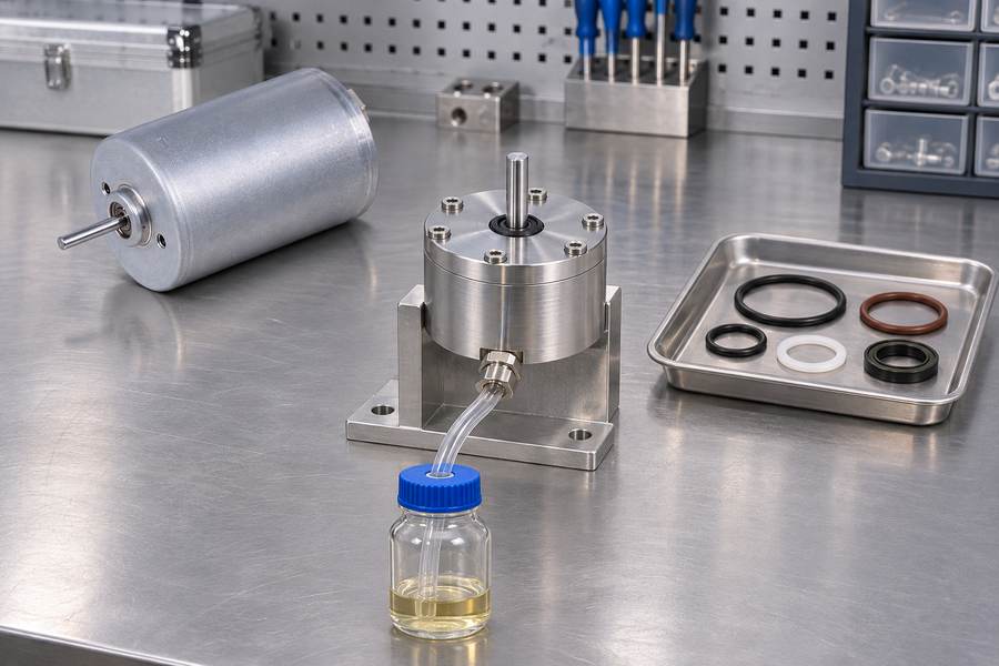
Where a drain connects to a collection line, consider backpressure and the possibility of a blocked or submerged outlet. A drain that cannot discharge under the actual installation condition may not provide the intended leakage path.
Map Leakage Paths and Containment
Trace the path fluid would take if the primary seal leaked, especially near bearings, windings, connectors, and electrical parts.
Decide whether leakage will be visible, collected, drained, or monitored. Any secondary containment needs defined geometry and capacity; an intermediate cavity is not a substitute for a suitable primary seal.
Separate Process Sealing from Electrical Enclosure Protection
Define the boundary protecting electrical components and review insulation exposure, connector placement, cable routing, and shared openings between pump and motor compartments.
A static IP rating describes enclosure protection under specified conditions; it does not establish rotating-shaft leakage resistance. Assess the process seal separately for pressure, speed, temperature, and fluid.
Specify and verify enclosure protection separately from process-seal performance.
Review the complete assembly, including cable entries and connectors, because the motor enclosure may have several potential ingress routes. A successful shaft-seal test does not verify those separate enclosure interfaces.
How Will the Shaft-Seal Interface Be Assembled, Maintained, and Validated?
Control Assembly and Installation
Define seal orientation, installation sequence, and tools. A lip can be cut or rolled while passing over a keyway, thread, sharp edge, or abrupt shaft transition.
Protect the shaft and seal from dirt, particles, and handling damage. Define alignment references and how the shaft enters the seal without twisting or displacing it.
If an assembly sleeve or temporary protector is needed to pass the seal over a shaft feature, identify its use in the work instruction. Remove temporary protection without dragging debris into the sealing area.
Plan Inspection and Replacement Access
Determine whether the seal can be inspected and replaced without dismantling unrelated components. Include service access in the mounting-interface design.
Define reusable parts and required replacements. A new seal may not work correctly against a worn, corroded, or damaged shaft track even if nominal diameter remains acceptable.
Specify how the track will be inspected and record wear, scoring, coating damage, or contamination against defined criteria.
Set Validation Conditions and Acceptance Criteria
Validation must represent the intended assembly and operating envelope. A static leak check does not prove performance during rotation, and one running condition cannot cover every specified condition.
Agree on fluid, pressure direction, temperature, speed, duration, and operating sequence. Define the leakage measurement method and acceptance threshold, including treatment of visible seepage or collected fluid.
Include relevant startup, shutdown, pressure transitions, and lubrication conditions. Monitor temperature, vibration, or current where useful, then inspect the seal and shaft track for damage or abnormal wear.
- Leakage criterion: State whether acceptance uses visible leakage, measured flow, or collected volume.
- Operating point: Record fluid, temperature, pressure direction, speed, and test duration.
- Measurement method: Identify the collection or inspection method and its resolution.
- Test sequence: Define startup, steady operation, shutdown, and required pressure transitions.
| Validation stage | Evidence to retain | Release decision |
| Design review | Approved interface drawing, seal definition, responsibility split, and operating envelope | Confirm that all parties agree on the sealing boundary and interfaces |
| Incoming and assembly inspection | Shaft dimensions, runout, surface condition, seal identity, and installation record | Confirm that the assembled parts match the approved specification |
| Functional validation | Test fluid, pressure, temperature, speed, duration, leakage observations, and measured operating data | Compare results with the agreed acceptance criteria |
| Post-test review | Seal and shaft inspection, deviations, corrective actions, and approval record | Release only the configuration that has passed the defined review |
Maintain Configuration Control
Link the seal, shaft drawing, chamber design, and test record to one assembly revision. This prevents test approval from being transferred to a configuration with different interfaces.
Changes to shaft material, coating, finish, bearing support, seal, chamber, fluid, or operating range require an impact review. Determine whether partial or full revalidation is needed.
Before release, retain the approved drawing, seal specification, responsibility matrix, material evidence, inspection results, test conditions, leakage criteria, and maintenance instructions.
Assign every open deviation an owner and disposition; do not release an interface with undefined responsibility or acceptance criteria.
The acceptance record should identify the tested hardware revision and any permitted production variation. This gives procurement, assembly, and service teams one controlled basis for deciding whether a delivered motor-pump combination matches the validated interface.