
Magnet retention in an inrunner BLDC motor must be assessed against rotor architecture, operating loads, temperature, and manufacturing controls. The retention label alone cannot establish suitability.
Buyers should request traceable calculations, controlled production records, and representative qualification evidence showing how the assembled rotor resists movement throughout its specified operating envelope.
How Are Magnets Retained in Different Inrunner BLDC Rotor Designs?
For an overview of configurable inrunner BLDC motor customization options, see Gian Transmission. Additional motor construction context is available through its brushless DC motor solutions.
Before comparing sleeves and adhesives, buyers must understand how the magnets are positioned and restrained within the actual rotor assembly. Different rotor architectures create different mechanical load paths.
Surface Permanent Magnet (SPM) Rotor Load Paths
In a surface permanent magnet rotor, magnets are attached to the outside of the rotor core. During rotation, centrifugal forces act radially outward and create a demand for reliable mechanical retention.
Adhesive bonding can secure the magnets to the rotor surface, while a retaining sleeve provides additional radial confinement. Some designs combine both methods to establish a more comprehensive retention arrangement.
The adhesive may maintain magnet positioning and transfer interface loads, while the sleeve restricts outward movement. Their individual contributions depend on contact conditions, geometry, material properties, and assembly design.
Buyers should also examine axial restraints. A sleeve that provides radial confinement does not automatically prevent magnets from moving along the rotor axis.
Important design variables include magnet mass, circumferential dimensions, radial position, adhesive coverage, sleeve thickness, and rotor diameter. These variables influence both the required retention capacity and the stresses experienced by individual components.
Interior Permanent Magnet (IPM) Rotor Load Paths
Interior permanent magnet rotors place magnets inside cavities within the rotor core. The surrounding steel structure, including bridges and ribs, contributes to magnet positioning and mechanical support.
Under rotation, centrifugal loading transfers through the magnet pockets and surrounding rotor material. Localized stresses may develop around bridge sections, pocket corners, and other geometric discontinuities.
Consequently, evaluating IPM retention requires more than reviewing adhesive properties or sleeve strength. Buyers need structural evidence showing how the rotor core supports the magnets under relevant operating conditions.
Adhesive may help secure magnets within their cavities, while additional mechanical features may provide supplementary restraint. The need for a retaining sleeve is determined by the rotor’s specific design.
Buyers should request analysis covering bridge strength, local deformation, stress concentrations, and fatigue where applicable. These characteristics cannot be inferred from the motor’s exterior appearance.
Why Buyers Must Confirm the Actual Retention Architecture
Published motor photographs generally show external housing, shaft, and mounting arrangements. They do not necessarily reveal internal magnet construction or the method used to prevent magnet displacement.
Gian Transmission offers inrunner motor customization, but published exterior images should not be treated as confirmation of a particular retention architecture. Buyers must obtain evidence for the proposed configuration.
Request rotor cross-sections, assembly drawings, material specifications, and descriptions of the retention components. The documentation should identify which components carry radial, axial, and other relevant mechanical loads.
The operating requirements must also be established before evaluating the design. Maximum operating speed, transient conditions, temperature range, acceleration, duty cycle, and environmental exposure all influence retention requirements.
What Evidence Should Buyers Request for Magnet Retaining Sleeves?
A retaining sleeve is a mechanical component whose performance depends on its material, dimensions, assembly condition, and interaction with the rotor. Buyers should request evidence covering the complete assembled structure.
Sleeve Materials, Geometry, and Mechanical Properties
Start by identifying the sleeve material and its relevant mechanical properties. Depending on the design, sleeves may use metallic materials or fiber-reinforced composites with different stiffness, strength, and thermal characteristics.
The material selection influences the sleeve’s ability to maintain confinement under centrifugal loading. Its mechanical response also changes with temperature and may depend on the manufacturing direction or reinforcement arrangement.
Request the following information:
- Material identification: The specified sleeve material, grade or construction, and applicable material documentation.
- Mechanical properties: Relevant strength, stiffness, and temperature-dependent properties used in the design calculations.
- Dimensional information: Sleeve thickness, inside and outside diameters, tolerances, and relevant geometric details.
- Construction method: Manufacturing and assembly information necessary to understand the sleeve’s structural behavior.
Geometry also affects the available electromagnetic air gap. A thicker sleeve may require changes to the surrounding rotor dimensions or electromagnetic design.
Therefore, buyers should confirm that mechanical retention requirements and electromagnetic clearances have been evaluated together. A mechanically acceptable sleeve is not automatically suitable for the complete motor design.
Interference Fit, Preload, and Hoop Stress
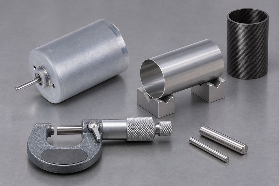
Some retaining sleeves use an interference fit or designed preload to establish radial contact pressure around the magnet assembly. This initial condition contributes to the sleeve’s mechanical confinement function.
Buyers should request calculations showing how the specified interference or preload was established. The analysis should consider sleeve dimensions, rotor geometry, material stiffness, and manufacturing tolerances.
Important calculation outputs include:
- Contact pressure: The predicted pressure between relevant components under assembly and operating conditions.
- Hoop stress: Circumferential stress developed within the sleeve during assembly and rotation.
- Rotor deformation: Changes in rotor dimensions caused by interference, preload, and operating loads.
- Local stress concentrations: Potentially critical regions around geometric transitions and interfaces.
- Engineering margins: The relationship between predicted stresses and applicable material limits.
Manufacturing variation matters because the actual interference may differ from the nominal drawing value. Buyers should understand how dimensional tolerances influence the assembled condition.
Excessive interference may create unwanted assembly stress or damage sensitive components. Insufficient interference may reduce the intended confinement, depending on the retention design.
For this reason, nominal sleeve dimensions alone do not demonstrate acceptable retention. The supplier should provide an assembly-level assessment supported by measurable dimensional acceptance requirements.
Thermal Expansion and Mechanical Stability
The sleeve, magnets, and rotor core may expand at different rates as temperature changes. This differential expansion can alter contact pressure, interface conditions, and internal mechanical stresses.
Buyers should request thermal-mechanical analysis covering relevant operating and non-operating temperatures. The analysis should identify whether the sleeve maintains its intended retention function throughout the specified temperature range.
Thermal cycling also deserves attention. Repeated heating and cooling may produce changing contact conditions, material fatigue, or other degradation mechanisms depending on the materials and construction.
The supplier should explain which material properties support the calculations and whether temperature-dependent behavior has been considered. Room-temperature calculations alone may not represent the complete operating envelope.
Where sleeve performance depends on initial interference, buyers should specifically request evidence that the required contact condition remains acceptable after relevant thermal exposure.
Electromagnetic Losses and Thermal Implications
Conductive sleeves may interact with changing magnetic fields and develop eddy currents. These currents can produce additional losses and contribute to rotor heating.
The magnitude of this effect depends on sleeve conductivity, geometry, electrical continuity, magnetic field conditions, and motor operating characteristics. Buyers should avoid assuming all metallic sleeves produce identical electromagnetic behavior.
Request electromagnetic analysis where sleeve conductivity may affect performance. Relevant evidence should address potential losses, associated heating, and their influence on magnet temperature and overall rotor operation.
Composite sleeves may have different electromagnetic characteristics, but their suitability still depends on structural properties, manufacturing quality, and operating conditions.
Mechanical strength should therefore be evaluated alongside electromagnetic and thermal implications. Selecting a sleeve solely because of its material strength overlooks other important design constraints.
Illustrative Calculation: Understanding Centrifugal Loading
The following simplified calculation illustrates why magnet mass, radial position, and rotational speed matter. It is an educational example, not a Gian Transmission product specification or an acceptable operating-speed recommendation.
For a rotating magnet segment treated as a concentrated mass, the centrifugal force can be estimated using:
F = m × r × ω²
Where:
- F: Centrifugal force in newtons.
- m: Magnet segment mass in kilograms.
- r: Radial distance from the rotation axis in metres.
- ω: Angular velocity in radians per second.
Angular velocity is calculated from rotational speed using ω = 2πn/60, where n represents revolutions per minute.
This simplified result does not establish the load carried by an adhesive bond or retaining sleeve. Actual load distribution depends on rotor geometry, contact conditions, component stiffness, and assembly details.
Buyers should request the supplier’s complete structural assessment rather than treating this basic calculation as proof of retention capability.
What Evidence Should Buyers Request for Adhesive Magnet Retention?
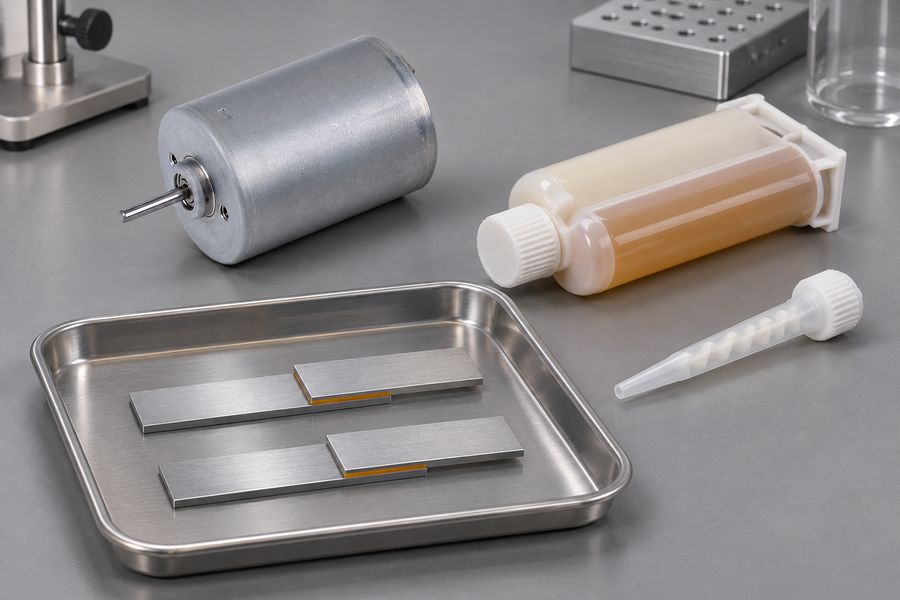
Adhesive retention depends on the complete bonded interface, not simply the adhesive material’s published strength. Bond performance varies with substrate preparation, adhesive-layer dimensions, cure conditions, temperature, and applied mechanical forces.
Adhesive Selection and Material Compatibility
Request the identity and traceability of the adhesive system specified for the rotor. The documentation should identify the relevant material properties and intended application conditions.
Compatibility must be evaluated between the adhesive, magnet coating, and rotor-core surface. A material that performs adequately on one substrate may behave differently when bonded to another.
Buyers should examine:
- Material properties: Relevant shear, tensile, and other mechanical characteristics.
- Temperature behavior: Changes in mechanical properties across the intended operating temperature range.
- Substrate compatibility: Suitability for the actual magnet coating and rotor-core materials.
- Aging characteristics: Available evidence concerning environmental exposure and long-term material degradation.
- Material traceability: Identification of the adhesive used in the qualified and supplied assemblies.
A published adhesive temperature rating does not independently establish the allowable operating temperature of a bonded rotor. Evaluate the bonded joint against the stresses and environmental exposure expected during service.
Surface Preparation, Bondline Control, and Curing
Surface preparation directly affects the quality of the adhesive interface. Contamination, inconsistent cleaning, unsuitable coatings, or inadequate preparation can reduce bonding reliability.
Buyers should request documented procedures describing how magnet and rotor surfaces are prepared before adhesive application. These procedures should identify relevant cleaning, treatment, and handling requirements.
Bondline thickness is another important control variable. An excessively thick, thin, or inconsistent bondline may change the mechanical behavior of the joint.
Request information covering:
- Surface preparation: Approved cleaning and treatment procedures for each bonded material.
- Bondline requirements: Specified thickness or gap limits and methods of maintaining consistency.
- Application control: Adhesive placement, coverage, and mixing requirements where applicable.
- Curing conditions: Documented time, temperature, and other process requirements.
- Process records: Evidence that production assemblies follow the approved bonding procedure.
Buyers should also establish how deviations are handled. Uncontrolled changes to preparation, application, or curing may create differences between qualified samples and production assemblies.
Bond Strength, Fatigue, and Environmental Aging
Adhesive joints can experience several types of mechanical loading. Shear loading acts along the bonded interface, while tensile loading pulls surfaces apart.
Peel and cleavage loading can create concentrated stresses near bond edges. These conditions are important because an adhesive joint may respond differently to localized separation than to relatively uniform shear loading.
Request evidence addressing the loading conditions relevant to the actual rotor geometry. A single adhesive strength value cannot represent every possible stress distribution within the assembled motor.
Fatigue is another consideration. Repeated acceleration, deceleration, temperature changes, and operating cycles may produce cumulative damage at the bonded interface.
Buyers should request relevant fatigue and thermal-cycling evidence. Environmental aging should also be considered where humidity, contamination, or other exposure conditions may affect the bonded assembly.
Adhesive coupon testing can help characterize material behavior, but it does not independently qualify a complete rotor. Representative assembly evidence is needed to account for actual geometry and manufacturing conditions.
Adhesive Bonding in Combined Retention Designs
Adhesive bonding and mechanical sleeves are not mutually exclusive. Many retention architectures can assign complementary functions to both components within the same rotor assembly.
For example, adhesive may secure magnet positioning against the rotor surface, while an outer sleeve provides radial confinement. The actual division of mechanical loads depends on the designed contact conditions.
In such arrangements, buyers should request calculations identifying the contribution of each retention component. The assessment should address interface stresses, sleeve loading, thermal expansion, and relevant interactions.
It is also important to establish whether the design depends on the adhesive for primary retention or uses it mainly for positioning and supplementary restraint.
Without this distinction, buyers may misunderstand the consequences of adhesive degradation or sleeve deformation. The complete assembly, rather than either material in isolation, must form the basis of acceptance.
How Should Buyers Compare Sleeve-Based and Adhesive-Based Retention?
A useful comparison examines the evidence required to establish performance under the same application conditions. Neither method is universally superior across different rotor geometries and operating requirements.
The following table provides a purchasing framework for evaluating documentation submitted by a motor manufacturer.
| Evaluation criteria | Sleeve-based retention | Adhesive-based retention | Combined retention |
| Primary evidence | Contact pressure and structural stress analysis | Bond stress and interface analysis | Interaction between mechanical and bonded retention |
| Material verification | Sleeve properties and dimensional records | Adhesive properties and compatibility records | Traceability of both material systems |
| Manufacturing control | Interference, preload, and assembly inspection | Surface preparation, bondline, and curing records | Inspection of both assembly processes |
| Thermal behavior | Expansion mismatch and retained contact pressure | Thermal aging and bond integrity | Combined thermal and mechanical assessment |
| Electromagnetic effects | Conductivity, eddy losses, and rotor heating | Relevant interface and material effects | Overall rotor electromagnetic assessment |
| Qualification evidence | Representative sleeve-equipped rotor testing | Representative bonded-rotor testing | Qualification covering the complete assembly |
What the Comparison Can and Cannot Establish
The comparison identifies different engineering responsibilities, but it cannot determine suitability without considering the complete motor design. A sleeve may address radial confinement without independently solving axial retention.
Similarly, adhesive properties alone cannot establish whether a bonded interface will remain acceptable under combined centrifugal and thermal loading.
Combined retention designs introduce additional interaction requirements. Buyers should establish whether the sleeve changes bondline loading, contact pressure, or the distribution of forces between components.
For IPM designs, rotor bridges, pockets, and surrounding core material require their own structural evaluation. Applying an SPM-oriented comparison without considering these features may lead to incomplete acceptance criteria.
The purchasing decision should therefore consider evidence quality, manufacturing repeatability, application suitability, and residual risks. A documented design with relevant qualification evidence is more meaningful than a general claim about retention technology.
What Manufacturing and Inspection Records Should Buyers Request?
Engineering calculations establish design expectations, but production controls demonstrate whether manufactured rotors actually match the evaluated configuration. Buyers should request traceable records linking materials, processes, and inspection results.
Material Traceability and Production Documentation
Each critical retention component should be identifiable through relevant production documentation. This includes magnets, sleeves, adhesives, and rotor-core materials used in the assembled product.
Request material records showing that supplied components correspond to approved specifications. Where material lots are controlled, the documentation should connect those records to the applicable rotor assemblies.
Production documentation should also identify the approved assembly procedures and design revisions. This allows buyers to distinguish the qualified configuration from later manufacturing changes.
For adhesive-based construction, records should cover preparation, application, and curing. For sleeve-based construction, they should cover relevant dimensions, interference or preload, and assembly inspection.
Critical Dimensional and Assembly Inspections
Inspection requirements should reflect the retention mechanism. Measuring external motor dimensions alone cannot establish whether the internal rotor assembly satisfies its approved design requirements.
For sleeve-equipped rotors, request dimensional inspection records covering relevant sleeve dimensions and assembled interference conditions. The acceptance requirements should correspond to the design documentation.
For bonded rotors, review documented controls for magnet positioning, bondline requirements, and curing verification. The supplier should explain which inspection methods are suitable for the actual assembly.
Additional mechanical inspections may include:
- Magnet positioning: Verification of location and alignment against the approved rotor drawing.
- Rotor geometry: Inspection of relevant diameters, concentricity, and dimensional relationships.
- Runout: Measurement against the applicable drawing and assembly acceptance requirements.
- Balancing: Documentation showing that the completed rotor meets its specified balancing requirements.
- Assembly condition: Inspection for visible damage, displacement, or other relevant manufacturing defects.
Balancing and runout checks are useful indicators of rotor assembly condition, but neither independently proves magnet-retention strength. They must remain separate from structural qualification evidence.
Acceptance Limits and Defect Handling
Written inspection limits and approval requirements should be established before manufacturing authorization. Statements such as properly assembled or adequately bonded provide insufficient guidance without defined inspection requirements.
Where a measurement is critical, the drawing or inspection plan should identify the applicable tolerance and measurement method. The supplier should also explain how inspection equipment and records are controlled.
Nonconforming assemblies require documented identification and disposition. Buyers should understand whether affected rotors are rejected, reworked through an approved procedure, or subjected to additional engineering assessment.
Inspection records must be traceable to the actual supplied configuration. A general quality certificate does not replace evidence covering the specific retention features and acceptance requirements.
What Design Analysis and Qualification Evidence Should Buyers Request?
Design analysis and physical qualification serve different purposes. Analysis predicts mechanical behavior under defined assumptions, while representative testing provides evidence about the assembled rotor under controlled conditions.
Design Calculations and Engineering Assumptions
Request design-specific calculations covering the complete retention arrangement. The documentation should identify the rotor geometry, material properties, operating conditions, and assumptions used in the analysis.
For SPM designs, relevant subjects include magnet centrifugal loading, sleeve stress, interface loading, and deformation. The analysis should reflect the actual relationship between magnets, adhesive, sleeve, and rotor core.
For IPM designs, examine the structural behavior of bridges, ribs, pockets, and other supporting features. Local stress concentrations and potential fatigue locations should receive appropriate attention.
Buyers should examine the following calculation inputs:
- Geometry: Actual dimensions and relevant manufacturing tolerances.
- Material properties: Properties appropriate to the specified temperature and loading conditions.
- Operating conditions: Relevant rotational speed, acceleration, temperature, and duty requirements.
- Boundary conditions: Assumptions describing contact, bonding, constraints, and component interaction.
- Acceptance basis: Applicable material limits, engineering margins, and documented failure criteria.
Analysis should also explain how uncertainties are handled. Differences between nominal and manufactured dimensions may influence the predicted stress and contact conditions.
Buyers should not accept simulation images without supporting assumptions and results. The useful evidence is the calculation methodology, input traceability, engineering interpretation, and relationship to the actual production design.
Representative Overspeed Qualification Evidence
Overspeed qualification can provide evidence about rotor integrity under a defined test condition. However, the usefulness of a report depends on how closely its specimen represents the proposed production assembly.
Request identification of the tested rotor configuration, including geometry, materials, sleeve construction, adhesive system where applicable, and manufacturing revision.
The test report should document the relevant conditions:
- Test configuration: The rotor construction and revision represented by the specimen.
- Test speed: The documented rotational condition and its relationship to the specified operating envelope.
- Temperature: The relevant test temperature and whether it represents the intended qualification condition.
- Duration: The time maintained under the documented test condition.
- Test sequence: Relevant acceleration, stabilization, and operating stages recorded in the report.
- Containment: The protective arrangements and test-facility controls used during testing.
- Results: Recorded observations, deviations, and acceptance decisions.
Buyers should establish whether the test addresses the relevant failure mechanisms. A single test condition may not represent every thermal, fatigue, or transient operating condition.
Overspeed testing should be performed through appropriately controlled qualification arrangements. Purchasing teams should evaluate the resulting documentation rather than attempting to establish acceptance through uncontrolled testing.
Passing a particular test does not establish unlimited safe operating speed. Nor does it automatically demonstrate long-term fatigue resistance under every possible duty cycle.
Post-Test Examination and Pass/Fail Assessment
Completing the test alone does not demonstrate that the rotor satisfies its acceptance requirements. Buyers should request documented inspections comparing the rotor’s condition before and after qualification testing.
For sleeve-based designs, inspect for permanent deformation, damage, or other changes that may affect mechanical confinement. Relevant dimensional measurements should be evaluated against established acceptance criteria.
For adhesive-based designs, examine available evidence of cracking, separation, magnet displacement, or other interface damage. Inspection methods should be appropriate for the bonded assembly and its construction.
IPM rotors also require attention to the surrounding core structure. Relevant inspection findings should address possible bridge damage, pocket deformation, or other structural changes identified during qualification planning.
Where applicable, compare rotor balance, runout, and relevant geometry before and after testing. Any differences should be evaluated rather than automatically classified as acceptable.
The final report should identify inspection methods, recorded findings, deviations, and the decision against predefined acceptance criteria. Surviving a test is not equivalent to demonstrating acceptable post-test condition.
Relevance and Limitations of Submitted Evidence
A test report from another rotor configuration cannot automatically qualify the proposed motor. Differences in magnet mass, sleeve construction, adhesive, rotor diameter, or assembly procedures may change the load distribution.
Buyers should compare the qualification specimen with the approved production drawings. Any differences should be documented and evaluated for their effect on the original engineering assumptions.
Prototype testing, design qualification, and routine production inspection serve separate purposes. Passing prototype qualification cannot verify that all later production units use equivalent materials and follow the same assembly procedures.
Where evidence does not cover the specified application, request a documented gap assessment. The supplier should identify unverified conditions and explain whether additional analysis or qualification is necessary.
Which Design or Manufacturing Changes Require Requalification?
Changes to a retention system may alter its mechanical load path, material behavior, or manufacturing consistency. Buyers should establish a formal process for reviewing changes against existing qualification evidence.
Changes to Rotor Geometry and Retention Materials
- Magnet changes: Different magnet dimensions, mass, grade, coating, or segmentation may alter retention loading and interface behavior.
- Sleeve changes: Material substitutions, thickness adjustments, interference changes, or construction modifications may affect confinement and stress distribution.
- Rotor-core changes: Revised bridge dimensions, pocket geometry, ribs, or other structural features may change the internal load path.
- Assembly changes: Modified component arrangements or restraints may affect the interaction between retention elements.
Changes to Adhesive and Manufacturing Processes
- Adhesive substitution: A different formulation may have different mechanical and thermal behavior.
- Surface preparation: Revised cleaning or coating procedures may influence interface quality.
- Bondline changes: Different thickness requirements or application methods may change joint performance.
- Curing changes: Modified process conditions may affect the final bonded interface.
- Production changes: New equipment, tooling, or manufacturing processes may require verification of process consistency.
Changes to Operating Requirements
Revised operating speed, temperature, acceleration, duty cycle, or environmental exposure may extend beyond the conditions covered by existing qualification evidence.
Buyers should require a documented engineering review identifying which original assumptions remain valid. The review should determine whether existing evidence is sufficient or additional qualification is necessary.
What Should Buyers Include in a Magnet Retention Evidence Checklist?
A purchasing specification should convert general retention expectations into identifiable documents, inspection requirements, and acceptance decisions. Use the items below to examine the supplier’s supporting documentation.
Essential Documentation and Verification Checklist
- Rotor configuration: Approved drawings identifying SPM or IPM construction, retention components, dimensions, and design revision.
- Material documentation: Traceable specifications for magnets, sleeves, adhesives, and rotor-core materials.
- Structural verification: Design calculations addressing relevant loads, stresses, deformation, and engineering margins.
- Manufacturing control: Records covering sleeve installation and, where relevant, surface preparation, adhesive-layer dimensions, and curing processes.
- Production inspection: Traceable dimensional, assembly, runout, and balancing records against approved requirements.
- Qualification evidence: Relevant engineering assessments and test records specifying the specimen design, test environment, exposure time, and documented outcomes.
- Post-test acceptance: Inspection findings, defined acceptance criteria, and documented treatment of deviations.
- Change management: Design revision control, material substitution procedures, and documented requalification decisions.
Important Questions to Ask the Motor Manufacturer
Before approving a proposed rotor design, buyers should obtain clear answers to questions that connect engineering assumptions with actual manufacturing evidence.
- Retention architecture: What physically prevents magnet movement under the specified operating conditions?
- Load distribution: Which components carry the primary centrifugal and other relevant mechanical loads?
- Combined retention: Are sleeves and adhesives used independently or as complementary retention features?
- Design verification: What calculations support the actual rotor geometry and material selection?
- Production consistency: How are material properties, dimensions, and critical assembly processes verified?
- Qualification relevance: Does the submitted test report represent the proposed production configuration?
- Post-test condition: Which inspection results demonstrate that the rotor meets its acceptance requirements?
- Change control: Which design, material, or process changes require additional engineering review?
Records and Acceptance Requirements Before Purchase Approval
Before releasing a purchase approval, request a controlled documentation package containing the approved rotor drawing, retention description, material records, and applicable structural calculations.
Attach the relevant production inspection requirements to the purchasing specification. Identify measurable dimensional limits, traceability expectations, and required records for sleeve installation or adhesive processing.
Qualification reports should identify the specimen configuration, test conditions, duration, containment arrangements, results, and post-test inspection findings. The supplier should demonstrate correspondence with the proposed production revision.
Define how deviations will be reported and approved. Material substitutions, revised retention geometry, or changes to critical bonding and sleeve processes should not be accepted solely through informal supplier notification.
Final acceptance should require agreement between the approved design, manufacturing records, qualification evidence, and documented inspection results. If a critical retention assumption remains unsupported, record it as an open technical issue rather than treating the motor as qualified.