
Rotor retention can limit an inrunner BLDC motor’s maximum speed because centrifugal loading increases approximately with speed squared. Magnets, retaining sleeves, adhesive joints, and rotor bridges must remain mechanically secure.
Calculated structural limits are not qualified operating speeds. Continuous and transient operation require defined conditions and evidence, while bearings, shaft dynamics, and electrical controls impose separate limits.
How Does Rotor Retention Limit the Maximum Speed of an Inrunner BLDC Motor?
What Is Rotor Retention in an Inrunner BLDC Motor?
An inrunner BLDC motor has a stationary outer stator surrounding a rotating assembly that carries permanent magnets. Retention features keep the magnets positioned against centrifugal loading and other operating forces.
The load path depends on rotor construction. Surface magnets may rely on a bonded joint and surrounding sleeve; buried magnets transfer loads through pockets, bridges, and webs.
Engineers should identify which components actually carry radial and circumferential loads. A motor’s outside diameter or housing shape cannot reveal the retention arrangement inside.
What Happens When Rotor Retention Fails at High Speed?
Retention failure may start locally rather than with complete rotor destruction. A separated bond, cracked bridge, or sleeve losing contact can allow a magnet to move.
That movement can change balance, reduce internal clearances, or cause contact with the stator. Damage can then spread faster than the controller can correct vibration.
- Magnet position: Check approved inspection evidence for movement, cracking, or changes from the original assembly geometry.
- Sleeve condition: Review records for dimensional change, cracks, or loss of intended restraint.
- Rotor bridges: Investigate local deformation and stress concentrations where buried magnet cavities narrow the core.
Rotor retention becomes the maximum-speed constraint when its allowable operating envelope is lower than the other applicable limits. Other components may reach their mechanical or operating limits before the retention system does.
Why Does Centrifugal Stress Increase with Rotor Speed?
How Does Rotational Speed Affect Centrifugal Stress?
For a rotating point of material, centrifugal acceleration varies with radius and the square of angular speed. Rotor stresses arising from rotation follow similar scaling for unchanged geometry.
Illustrative calculation, not a motor rating: Increasing speed from 20,000 to 30,000 rpm multiplies the rotational stress contribution by approximately (30,000/20,000)², or 2.25.
The example does not predict failure speed. Sleeve interference, residual manufacturing stress, heating, and changing contact conditions can alter total stress and the location of its maximum.
How Do Rotor Diameter and Material Properties Influence Stress?
Material at a larger radius experiences greater acceleration at the same rpm. Magnet density, sleeve thickness, and the distribution of mass affect the resulting loads.
Material stiffness influences deformation and contact pressure, while strength and fatigue behavior constrain acceptable stress. Sharp transitions and narrow webs can concentrate stress locally.
For comparison, engineers need actual rotor dimensions, material data, and assembly conditions. A published speed figure from a different rotor diameter cannot be transferred safely.
How Do Different Rotor Retention Designs Affect Maximum Speed?
Surface-Mounted Magnet Rotor Retention
Surface-mounted magnets sit around the rotor core. Bonding holds them during manufacture and may carry operating loads, while a fitted sleeve can provide circumferential restraint.
The sleeve must resist its own rotation-induced stress while maintaining effective control of magnet movement. Greater thickness may improve strength but consumes radial space near the air gap.
Inspection requirements should cover magnet placement, bonding process records, sleeve dimensions, and fit. None of those checks individually establishes a qualified maximum speed.
How Buried Magnets Are Secured Within the Rotor
In this rotor configuration, specially formed cavities in the core accommodate the permanent magnets. Bridges and webs between cavities and outer surfaces carry load while preserving the rotor’s magnetic structure.
Thin bridges may experience significant local stress, particularly near pocket corners. Manufacturing variation or damage at these features can change the predicted structural behavior.
Evaluation should examine bridge geometry, material properties, and expected deformation. A buried magnet is not inherently more secure at speed than a properly engineered sleeved magnet.
Surface-Mounted vs. Interior Magnet Retention
These designs distribute centrifugal loads differently, so evidence for one cannot be substituted for the other. The relevant acceptance criteria follow the actual retention path.
| Comparison factor | Surface-mounted rotor | Interior magnet rotor |
| Magnet position | Rotor outer surface | Internal core pockets |
| Typical restraint | Bond and/or surrounding sleeve | Core bridges, webs, surrounding material |
| Structural concern | Sleeve hoop stress, bond separation, contact loss | Bridge stress, local deformation, cracking |
| Temperature concern | Fit, bond behavior, differential expansion | Pocket stresses, differential expansion |
| Useful verification | Fit, bond process, sleeve geometry and analysis | Pocket geometry, bridge condition and analysis |
Neither design has a universal speed advantage. Rotor diameter, materials, temperature, manufacture, and demonstrated qualification determine whether the proposed construction meets its intended duty.
How Do Sleeve Stress, Temperature, and Adhesive Durability Affect Rotor Retention?
Hoop Stress and Retaining Sleeve Strength
Hoop stress acts around the circumference of a retaining sleeve. It arises from rotational loading and may also reflect contact pressure introduced during assembly.
A sleeve that is strong in isolation can still be unsuitable if the assembled rotor loses contact pressure or exceeds allowable local strain at operating conditions.
Design review should compare sleeve thickness, material properties, stress distribution, and the intended speed range. Inspectors should verify dimensions against controlled drawings rather than nominal labels.
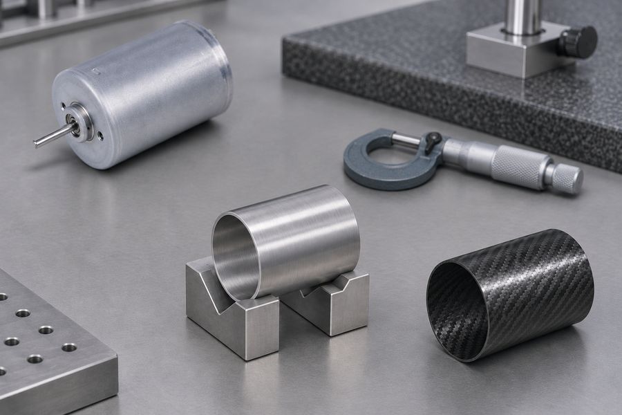
Interference Fit and Contact Pressure
An interference fit establishes initial contact pressure between mating rotor components. That pressure helps keep magnets restrained as the assembly accelerates and expands.
Too little interference may permit separation during rotation; too much can overstress the sleeve or damage magnets during assembly. The acceptable fit requires calculation and process control.
Check measured mating dimensions, temperature at measurement, assembly method, and relevant tolerances. A recorded nominal interference without actual component measurements provides limited evidence.
Thermal Expansion and Rotor Retention Integrity
Magnets, steel cores, and sleeve materials do not necessarily expand at the same rate. Their changing dimensions can alter interface pressure and redistribute mechanical stress.
Cold starts and sustained hot operation may produce different limiting cases. Thermal cycling also introduces repeated changes in stress at bonded and mechanically constrained interfaces.
Engineers should evaluate the intended rotor temperature range, not just ambient temperature. Acceptance records should identify which temperatures the fit and structural calculations cover.
Adhesive Bond Strength, Aging, and Mechanical Backup
Bond reliability depends on more than the adhesive’s published strength. Surface contamination, bond thickness, curing conditions, and magnet coating compatibility affect the actual joint.
Prolonged heat, cycling, vibration, and exposure to relevant chemicals may change joint properties. Qualification must account for the service environment and expected operating life.
- Preparation: Record cleaning and surface-treatment requirements, including how compliance was verified.
- Application: Control adhesive identity, shelf condition, application coverage, and the intended bond-line geometry.
- Cure: Retain the required process settings and traceable evidence that the assembled parts followed them.
- Backup restraint: Establish whether a sleeve or other feature actually retains magnets after a defined bond failure.
Two retention features do not necessarily provide independent redundancy. A shared temperature excursion, assembly defect, or excessive stress can compromise both at once.
What Other Factors Can Limit Inrunner BLDC Motor Speed?
Rotor Balance and Vibration
Rotor imbalance produces rotating forces that generally increase with speed squared. Those forces affect bearings, shaft deflection, and vibration transmitted to connected equipment.
Balancing addresses mass distribution; it does not prove sleeve strength or bridge integrity. A rotor can meet its balance requirement yet remain structurally unqualified for the requested speed.
Review balance acceptance criteria, measurement speed, assembly state, and any subsequent machining or magnet replacement. An altered rotor should not inherit earlier balance evidence automatically.
Bearing Speed and Operating Conditions
Bearing limits depend on type, lubrication, fit, temperature, and applied radial or axial loads. Increased speed can change heating and the available lubrication regime.
Check the bearing arrangement under actual coupled loads, including belt tension or other external forces where applicable. Bearing suitability does not demonstrate magnet retention strength.
Conversely, a mechanically sound rotor may still require a lower operating speed because of bearing temperature or life constraints. Keep those decisions separately documented.
Shaft Strength and Critical Speed
Shaft diameter, unsupported length, stiffness, and attached inertia influence bending behavior. A rotating assembly may encounter critical speeds at which dynamic response increases sharply.
Evaluate the installed rotor, bearings, and connected components as a system. A calculation for the bare shaft may not represent the supported assembly’s vibration response.
Shaft critical speed is not rotor burst speed. Records should identify relevant modes and any operating restrictions without presenting resonance avoidance as retention qualification.
Electrical, Controller, and Thermal Limitations
Voltage, back-EMF, winding design, available current, and thermal performance can limit attainable speed. Controllers may also apply command limits or detect excessive speed.
Neither a commanded setpoint nor a brief no-load run proves the rotor’s structural capability. Control settings must be consistent with separately qualified mechanical and thermal limits.
Document electrical operating boundaries independently. The usable speed envelope is constrained by whichever relevant mechanical, dynamic, electrical, or thermal requirement is most restrictive.
How Can Engineers Calculate and Validate Maximum Rotor Speed?
Calculating Rotor Retention Strength
Structural calculations estimate stress, deformation, and contact behavior across the specified speed and temperature range. Detailed models can examine local conditions beyond simplified hand calculations.
The assessment needs traceable geometry, material data, fit tolerances, temperature assumptions, and realistic boundary conditions. Adhesive properties and manufacturing variation matter where bonds carry load.
- Surface magnets: Check sleeve stress, interface contact, magnet loading, and bond behavior where relevant.
- Buried magnets: Check bridge stresses, pocket corners, local deformation, and magnet constraint.
- Assembly range: Assess relevant tolerance extremes rather than calculating only an ideal nominal rotor.
A predicted threshold is sensitive to assumptions and uncertainty. It should not be published as a safe operating speed without a defined engineering acceptance basis.
Distinguishing Structural Limits from Qualified Operating Speeds
A calculated structural limit estimates a failure-related boundary under stated assumptions. A qualified continuous speed is an approved sustained operating limit under defined service conditions.
A qualified transient speed permits a specified short-duration event, not indefinite operation. Duration, frequency, temperature, and loading must be identified for the transient claim.
Controller-commanded speed is simply what the control system requests. Actual speed can differ, and neither value replaces documented rotor qualification or an appropriate overspeed protection strategy.
Proof Overspeed Testing and Rotor Qualification
Proof overspeed testing applies a specified speed under controlled conditions to assess integrity against agreed acceptance criteria. It does not measure burst speed unless failure is deliberately investigated.
A proof result applies to the tested configuration and conditions. Changes to magnet arrangement, sleeve fit, materials, or production processes may require additional engineering review.
Testing belongs in qualified facilities with engineered containment, remote operation where appropriate, and controlled inspection procedures. Improvised overspeed trials expose personnel to unacceptable fragment hazards.
Useful records identify test speed, duration, temperature, specimen traceability, monitoring, and post-test acceptance findings. Passing one proof condition does not authorize sustained operation there.
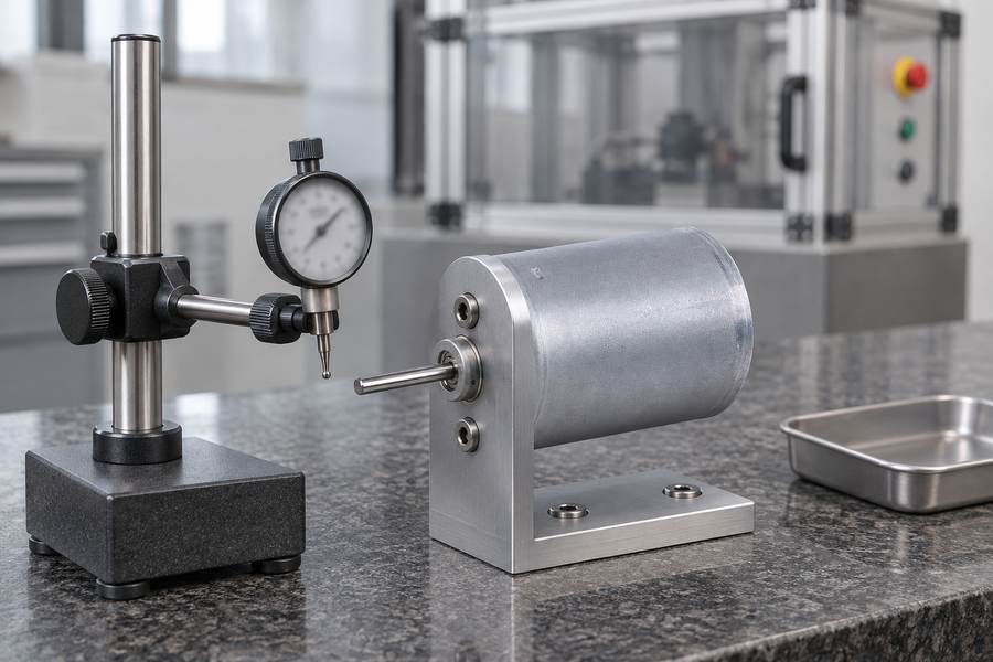
Understanding Rotor Speed Limits and Test Evidence
Purchasing specifications should use unambiguous speed terminology. A single figure described as maximum rpm cannot establish whether it represents an electrical setting, sustained rating, or proof condition.
| Speed category | Meaning | Evidence or boundary to request |
| Calculated structural limit | Analysis-based mechanical threshold | Model assumptions, material data, stress criteria |
| Qualified continuous speed | Approved sustained operating limit | Duty, temperature, load, qualification evidence |
| Qualified transient speed | Approved short-duration limit | Duration, repetition, load, qualification evidence |
| Proof overspeed | Controlled integrity test condition | Test procedure, specimen, inspection acceptance |
| Controller-commanded speed | Requested rotational speed | Control settings, feedback, protective behavior |
| Rotor burst speed | Destructive failure condition | Specific destructive evidence or supported analysis; not an operating rating |
Separate these terms in drawings, purchase specifications, and test reports. An overspeed proof figure should never be copied into the continuous operating field.
What Should Engineers and Buyers Check When Selecting a High-Speed Inrunner BLDC Motor?
Define the Required Speed and Operating Conditions
Begin with the machine’s actual duty rather than a desired headline rpm. Continuous and transient demands may create different structural and thermal limiting cases.
- Speed profile: Record sustained speed, highest credible transient speed, acceleration, deceleration, and event frequency.
- Environment: Define rotor-relevant temperature conditions, cooling assumptions, and possible chemical exposure.
- Mechanical interface: Record shaft coupling, supported loads, installed orientation, and attached inertia.
- Abnormal conditions: Identify credible controller or load faults that could produce overspeed, with planned protective responses.
Provide the same duty definition to design, validation, and purchasing teams. Otherwise, an apparently matching speed figure can conceal incompatible operating assumptions.
Verify Rotor Retention Design and Qualification Evidence
Request a description of the actual retention method and its load path. Do not infer a sleeved rotor, bonding arrangement, or buried-magnet construction from exterior photographs.
For sleeved designs, seek dimensional and fit controls alongside stress assessments. For buried designs, seek bridge geometry and local strength evaluations. Both need applicable temperature coverage.
Distinguish design calculations from qualification records and production inspections. A material certificate cannot demonstrate completed assembly fit, while a balance report cannot demonstrate retention integrity.
Evaluate Custom Inrunner BLDC Motor Requirements with Gian Transmission
Gian Transmission offers customization of inrunner geometry, shaft configuration, windings, voltage, and power output. Its custom inrunner brushless DC motor options provide a starting point for requirements discussions.
Any relevant change in diameter, rotor layout, or shaft arrangement should trigger review of the mechanical analysis. Winding changes may alter electrical behavior without increasing allowable retention stress.
The broader brushless DC motor range describes available motor categories, not a universal rotor burst rating. No configuration-specific retention certification should be presumed.
Before acceptance, establish a controlled record package identifying the exact drawing revision, material and process traceability, dimensional checks, approved operating envelope, and qualification basis.
- Design acceptance: Confirm the rotor retention load path and applicable structural assessment for the selected configuration.
- Manufacturing acceptance: Match sleeve, bridge, bond, and balance inspection records to the specified assembly revision.
- Test acceptance: Require documented conditions, measurements, inspections, and disposition against agreed criteria.
- Operating release: Record continuous and transient limits separately, including temperature, load, duration, and controller safeguards.
- Change control: Define when a revised magnet, sleeve, shaft, adhesive, or process requires renewed engineering approval.
Release the motor for its intended duty only when the requirements, retained evidence, and actual supplied configuration agree. Record any unresolved limits as explicit acceptance holds.