
Nearby magnets can disturb Hall feedback in an outrunner BLDC motor by adding stray flux to the rotating rotor field. Switching edges may shift, state durations may become unequal, or expected transitions may disappear.
For Gian Transmission assemblies, diagnosing these effects requires independent rotor-angle measurements, synchronized Hall waveforms, and representative magnetic, electrical, and temperature conditions.
How Do Nearby Magnets Change the Magnetic Field at Hall Sensors?
Magnetic Field Superposition and Sensor Orientation
In an outrunner BLDC motor, permanent magnets are mounted on the rotating outer bell, while the stator and its associated Hall sensors remain stationary.
As the rotor turns, magnetic flux changes at each Hall sensor. The sensor detects this changing field and provides position information for the motor controller.
When another permanent magnet is installed nearby, its magnetic field combines with the rotor field. This interaction follows magnetic field superposition rather than simple addition of field magnitudes.
The Hall element responds to the component of the combined magnetic field along its sensitive axis. Field components perpendicular to that axis do not contribute directly to the ideal sensing signal.
A simplified expression is B_sensed(θ) = [B_rotor(θ) + B_external] · n, where n represents the Hall sensitive-axis direction and θ represents rotor angle.
For a fixed external magnet, B_external can remain approximately constant in stator coordinates. However, its effect on switching is angle-dependent because B_rotor changes as the rotor rotates.
Consequently, a constant magnetic bias does not necessarily produce identical angular shifts at every switching edge. The shift depends on local field slope and switching direction.
External magnet orientation is especially important. Reversing its polarity or rotating its position can change whether the projected field reinforces or opposes the rotor field.
Hall Sensor Thresholds, Hysteresis, and Magnetic Operating Margin
Digital Hall sensors change output states when the magnetic field reaches specified switching thresholds. These thresholds must be taken from the actual sensor documentation.
The operate threshold, Bop, identifies the field condition that triggers one output transition. The release threshold, Brp, identifies the condition required for the opposite transition.
The difference between these thresholds establishes magnetic hysteresis, helping prevent unstable switching when the sensed field fluctuates near a transition.
Hall devices do not all respond identically. Latching and other switching devices can use different threshold polarities, sensing directions, and output behavior.
For a particular Hall latch, both the sensitive-axis orientation and the specified Bop and Brp values determine how an external magnetic field influences its switching.
An acceptable design therefore needs sufficient magnetic margin to cross both required thresholds under its specified operating conditions, including manufacturing and temperature variations.
The following factors should be considered together rather than evaluated through magnet distance alone:
- Magnet orientation: Determines how much external magnetic flux projects along the Hall sensitive axis.
- Separation distance: Influences field strength at the sensor, although the relationship depends on magnetic geometry and surrounding materials.
- Sensor tolerance: Changes the actual switching thresholds between devices and production units.
- Temperature: Can affect sensor thresholds, rotor magnet flux, and magnetic properties of nearby components.
- Rotor-field margin: Determines whether the useful magnetic signal can still cross the required switching thresholds.
A magnet separation distance that provides acceptable Hall feedback in one assembly may not deliver the same performance in a different motor configuration. Magnet strength, pole arrangement, sensor orientation, and nearby magnetic materials may differ.
What Hall Feedback Problems Can Nearby Magnets Cause?
Shifted Switching Angles and Unequal Hall States
Hall switching should occur at predictable electrical rotor angles for a specified motor and sensor arrangement. Nearby magnetic fields can change those angular positions.
When external flux reinforces the rotor field near a threshold crossing, the sensor may switch earlier. Opposing flux can delay the crossing or prevent it.
The effect can differ between rising and falling transitions because the rotor field has different slopes and the Hall device uses different switching thresholds.
For example, one Hall output may remain high across a larger angular interval while its low interval becomes shorter, despite unchanged mechanical rotor speed.
The resulting waveform can appear asymmetric. This does not necessarily indicate an electrical timing error because the underlying disturbance may be magnetic.
Unequal state durations can also occur naturally through sensor placement errors or magnetic geometry. Comparing against the established baseline helps isolate external interference.
For diagnosis, express each edge position in electrical degrees and compare corresponding transitions at equivalent rotor positions, rather than comparing pulse widths alone.
Missing Transitions and Stuck Hall Outputs
A stronger external field may shift the combined magnetic signal far enough that it never crosses a required switching threshold during part of the rotation.
If the field fails to reach Bop or Brp, a Hall output can remain latched in its previous state instead of changing as expected.
This creates a genuinely missing magnetic transition, not merely a delayed edge or a short electrical glitch in the signal wiring.
The controller may then receive an incomplete rotor-position sequence. Depending on its configured behavior, this can affect starting, commutation timing, torque production, or fault detection.
A missing edge can be especially important during low-speed operation because Hall feedback may provide the controller’s principal information about rotor position.
At higher speeds, incorrect transition timing can still influence commutation. The practical consequence depends on the driver algorithm and the severity of the distortion.
Do not assume that increasing input filtering will resolve the problem. Filtering may suppress electrical noise, but it cannot recreate a physically absent threshold crossing.
Interpreting 60° and 120° Hall Feedback
Hall feedback must be evaluated against the approved sensor arrangement and controller convention. Different 60° and 120° configurations can produce different state sequences.
These angular descriptions commonly refer to electrical spacing or signal relationships, not necessarily the physical mechanical spacing measured around the motor housing.
Electrical angle depends on the number of magnetic pole pairs. The basic relationship is electrical angle = mechanical angle × pole-pair count.
For an illustrative motor with seven pole pairs, 10 mechanical degrees correspond to 70 electrical degrees. This is an example, not a Gian Transmission motor specification.
When comparing Hall transitions, the pole-pair count must therefore be included. Mechanical shaft-angle measurements cannot be directly interpreted as electrical-angle intervals.
A correctly configured Hall system should follow its approved six-state commutation sequence. The expected bit patterns depend on sensor arrangement, wiring order, polarity, and interpretation.
Under common 120° Hall conventions, 000 and 111 are not part of the normal six-state sequence. However, these patterns can be legitimate under certain 60° conventions.
Neither pattern should be universally classified as invalid without checking the approved motor-driver mapping. Sequence correctness and transition timing must be evaluated together.
| Observed Hall Symptom | Possible Magnetic Mechanism | Required Diagnostic Evidence |
| Switching edge occurs early | External field causes an earlier threshold crossing | Compare edge angle with the baseline using an independent rotor reference |
| Switching edge occurs late | External field delays the required threshold crossing | Measure the angular displacement with and without the magnetic source |
| Unequal Hall-state durations | Rising and falling transitions shift by different amounts | Compare complete electrical-cycle waveforms at equivalent operating conditions |
| Hall output remains high or low | Combined field does not cross the required Bop or Brp threshold | Check the magnetic source position and the absent transition across rotor angles |
| Unexpected 000 or 111 state | Possible interference, incorrect mapping, or valid convention-dependent state | Verify the approved 60° or 120° Hall-state sequence before classifying the condition |
| Irregular isolated pulses | Electrical interference or signal connection problems may be present | Inspect signal integrity, supply stability, and synchronization with rotor angle |
How Can You Distinguish Magnetic Interference from Other Hall Feedback Faults?
Magnetic Interference from Nearby Components
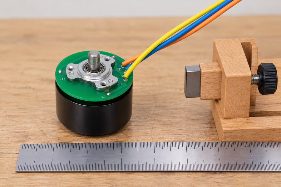
Document the magnet’s position and orientation relative to the Hall sensors. This unpowered layout illustrates positioning only; the depicted gap is not a recommended clearance or proof of magnetic immunity.
The most useful diagnostic comparison isolates the external magnetic source while keeping the motor, sensor wiring, measurement equipment, and rotor-angle reference unchanged.
First, record a baseline with nearby magnetic components removed or repositioned where the mechanical design and approved procedures permit.
Then repeat the measurement with each magnet installed at its intended location. Observe whether switching-angle changes follow the magnet’s position or polarity.
A magnetic cause becomes more plausible when the same angular displacement appears repeatedly after reinstalling the source in the same orientation.
However, removing a magnet must not unintentionally change sensor alignment, cable routing, mechanical loading, or measurement geometry. Those changes would weaken the comparison.
Moving magnetic components require additional attention. An actuator magnet may expose the Hall sensors to different fields across its complete operating travel.
If nearby electromagnets are involved, their current-dependent operating states should also be reproduced because the external field may change during normal machine operation.
Electrical Interference and Wiring Problems
Hall feedback can also become distorted through electrical disturbances. PWM switching, poor grounding, unstable sensor supplies, and damaged connections can produce unexpected signal behavior.
Electrical noise often creates additional pulses, unstable voltage levels, or switching glitches that do not correspond consistently to a physical rotor-angle position.
Measure the Hall supply, signal outputs, and reference ground with suitable instruments. The measurement arrangement must avoid introducing additional grounding or probing errors.
Inspect connector retention, cable routing, signal return paths, and the controller input requirements. A correct magnetic transition may still be misread electrically.
Filtering and input hysteresis can improve resistance to appropriate electrical disturbances. Their settings must preserve genuine Hall transitions over the required operating-speed range.
The selected BLDC motor driver should be reviewed for compatible Hall-state interpretation, input characteristics, and commutation settings before changing the sensing arrangement.
If the magnetic signal never crosses the sensor threshold, additional electrical filtering cannot restore the missing rotor-position information. The magnetic condition must be corrected.
Rotor Magnet and Mechanical Problems
Not every Hall waveform abnormality originates from an external magnet. Rotor eccentricity, incorrect sensor alignment, and changes in rotor magnetic properties can produce similar symptoms.
An outrunner’s rotating bell must maintain its intended geometry relative to the stationary sensor assembly. Mechanical runout can change the local magnetic field at the sensors.
Bearing condition, rotor alignment, and assembly damage should therefore be reviewed when Hall timing changes persist after external magnetic sources are removed.
Possible rotor magnet damage requires separate evidence. Hall waveforms alone cannot establish irreversible demagnetization because sensor position, temperature, and electrical conditions also influence switching.
Comparing repeatable rotor-angle-related behavior before and after changing the external magnetic arrangement helps distinguish an installation problem from a persistent motor condition.
Where inspection or magnetic measurement is necessary, follow the approved motor service boundary. Disassembly should not be assumed permissible simply because interference is suspected.
How Can You Reduce Magnetic Interference in an Outrunner Assembly?
Adjust Magnet Placement and Sensor Geometry
Physical separation is often worth evaluating first because it can reduce interference without changing the Hall sensor or controller configuration.
However, magnetic field strength depends on source geometry, orientation, surrounding materials, and distance. No universal safe separation can be established for every assembly.
Changing the orientation of an external magnet may reduce its projected field along the sensor’s sensitive axis, even when the available separation remains unchanged.
A practical layout review should identify all nearby magnetic components, including permanent magnets, magnetized structural parts, and energized devices that can produce local fields.
Any proposed relocation must preserve the intended mechanical function, available clearances, assembly tolerances, and access requirements for installation and maintenance.
Hall sensor repositioning is another possible design option, but it changes the sensor’s relationship with the useful rotor field and may require controller timing verification.
Review the installation geometry with Gian Transmission when specifying an outrunner BLDC motor for equipment containing nearby magnetic components.
After any geometric modification, measure the actual switching angles and state sequence. A layout that appears magnetically favorable must still satisfy the required motor operation.
Assess Magnetic Shielding Materials and Geometry
A surrounding metal enclosure does not automatically protect Hall sensors from nearby permanent magnets. Shielding behavior depends strongly on the material and magnetic-field characteristics.
Aluminum and copper are not generally effective barriers against static magnetic fields. Although these materials can attenuate certain time-varying electromagnetic fields, they generally do not provide effective shielding against static magnetic fields.
Suitable high-permeability materials can redirect magnetic flux under certain conditions. Their effectiveness depends on material properties, thickness, shape, placement, and magnetic loading.
Shielding geometry must be evaluated carefully because corners, openings, and available flux paths affect the local field distribution near the Hall sensors.
Magnetic saturation is another consideration. A shield that becomes saturated under an external field may no longer provide the expected reduction in interference.
A shield can also influence the useful rotor magnetic field. Redirecting that flux may change switching angles or reduce the magnetic margin available to the sensors.
Magnetic shielding should therefore be assessed as part of the complete motor assembly rather than selected solely from a material description or simplified distance calculation.
Any shielding modification requires renewed measurements of Hall transitions, motor operation, mechanical clearance, and relevant temperature conditions. No shielding arrangement guarantees universal immunity.
Improve Signal Integrity Without Masking Magnetic Faults
Good Hall wiring practices remain important even when magnetic interference is the main concern. Electrical noise and magnetic bias can coexist within the same assembly.
Route sensor wiring away from high-current switching conductors where practical, while maintaining suitable signal return paths and the approved connector arrangement.
Review supply decoupling, grounding, and controller input filtering according to the selected electrical interface. Avoid assuming that stronger filtering always improves feedback quality.
Excessive filtering can delay valid transitions or suppress short pulses at higher speed. These effects should be assessed against the motor’s required commutation behavior.
If an external magnetic field prevents a physical Hall transition, the corrective action must address field geometry, sensing margin, or another approved position-feedback approach.
Electrical and magnetic countermeasures should be validated separately before testing their combined performance. This distinction makes subsequent design changes easier to evaluate.
How Should You Validate Hall Feedback in the Complete Motor Assembly?
Establish a Controlled Baseline
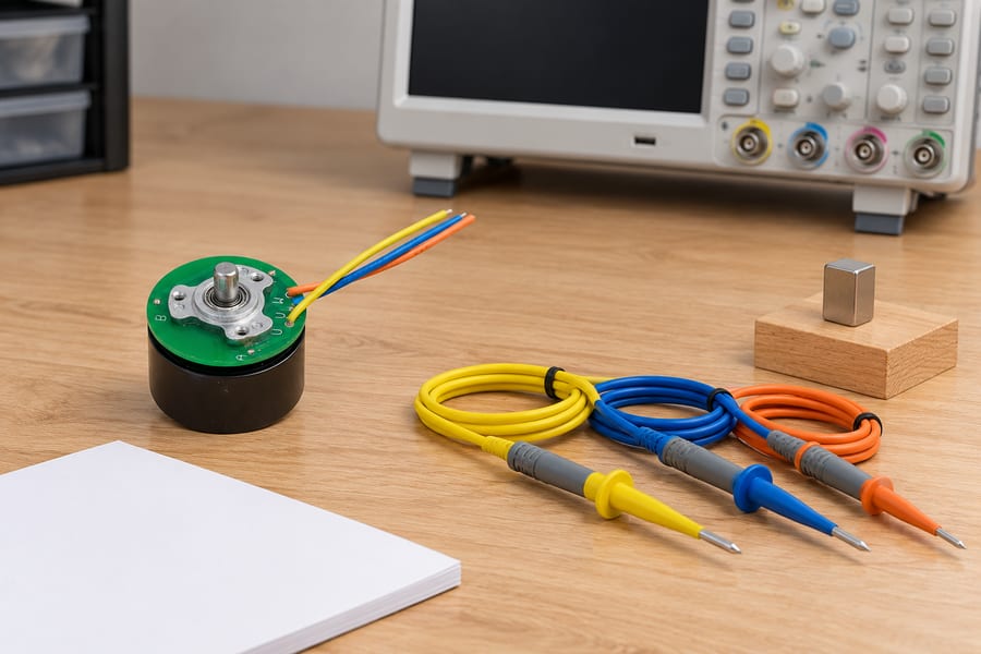
Prepare synchronized Hall-channel recording together with an independent rotor-angle reference. The disconnected equipment shown illustrates planning, with no measured waveforms or confirmed sensor connection implied.
Assembly validation begins with a repeatable baseline that links Hall output transitions to independently measured rotor angle. Motor controller estimates alone may not provide an independent reference.
Use an appropriate encoder, angular measurement system, or controlled reference fixture capable of resolving the switching-angle changes relevant to the application.
Synchronize the rotor-angle reference and all Hall channels within the same measurement system or through a verified common timing reference.
Record the actual pole-pair count and identify the mechanical reference position. Convert measured mechanical angles into electrical angles before evaluating commutation-sector spacing.
Baseline measurements should cover complete electrical cycles, not merely one selected rising edge. Each Hall channel can respond differently to an external magnetic bias.
Document the approved state sequence, sensor supply conditions, direction of rotation, speed, temperature, and controller configuration alongside the captured waveforms.
Where practical, establish this baseline without the external magnetic sources installed. If they cannot be removed safely, document the existing magnetic configuration explicitly.
The baseline should also include repeated measurements after controlled remounting or positioning operations where such operations are part of normal assembly.
Reproduce Actual Magnetic Operating Conditions
A useful interference test reproduces the magnets as they will exist in the finished equipment, including their positions, polarities, orientations, and operating movements.
Testing a loose magnet at an arbitrary distance cannot establish the behavior of the installed assembly because the resulting field geometry may be substantially different.
For moving components, evaluate the relevant positions throughout their travel. The maximum interference may occur at an intermediate position rather than either mechanical endpoint.
Consider magnetic components energized during operation, including current-dependent fields. Stator current and surrounding electromagnetic devices may modify the local field during testing.
Representative operating conditions should include:
- Startup: Verify that the initial Hall states support the approved starting and commutation sequence.
- Steady rotation: Compare transition angles and state durations at relevant operating speeds.
- Reversal: Check switching behavior in both directions where reversing operation is required.
- Current extremes: Evaluate relevant winding-current and nearby electromagnetic operating conditions.
- Temperature extremes: Repeat measurements at the specified cold and hot operating conditions.
- Assembly variation: Include relevant placement tolerances and repeatable installation conditions.
Testing should remain within approved electrical, thermal, and mechanical operating limits. Rotating components require appropriate guarding and controlled access during measurement.
External magnets should be repositioned only through an approved procedure that prevents unintended rotor movement, contact with rotating components, or damage to the assembly.
Smartphone compass readings are not suitable quantitative proof of Hall interference or immunity. They do not establish the required local sensitive-axis field and switching thresholds.
Assess Hall Feedback Performance Against Acceptance Requirements
Validation should compare corresponding switching events at equivalent rotor positions and operating conditions. Differences in speed or measurement reference can otherwise create misleading results.
Measure the angular displacement of each transition relative to the baseline, including both rising and falling edges for every Hall channel.
Check the complete Hall-state sequence and identify missing transitions, unexpected repeated states, and any state patterns inconsistent with the approved controller convention.
Evaluate state durations in electrical degrees, particularly when comparing different speeds. Time-domain pulse widths alone cannot separate angular distortion from changing rotational speed.
Repeat the measurements across the specified temperature and current conditions. Account for variations in Hall sensor switching thresholds and measurement instrument uncertainty when assessing the significance of differences between test results.
Commutation performance should also be checked under representative starting, loading, and reversal conditions. Correct-looking waveforms do not automatically establish acceptable motor behavior.
Acceptance criteria must come from the actual motor-driver requirements and intended application. No universal Hall edge-shift limit or magnetic immunity threshold applies to every design.
| Test Condition | Required Measurements | Comparison Method | Acceptance Basis |
| Baseline with controlled magnetic surroundings | Hall waveforms, rotor angle, speed, and sensor supply | Establish switching-angle and state-sequence references | Approved motor and controller configuration |
| External magnets in installed positions | Hall edge angles and state durations | Compare corresponding transitions against baseline | Application-defined allowable timing variation |
| Changed magnet polarity or orientation | Direction and magnitude of edge displacement | Correlate changes with documented field orientation | Specified assembly magnetic configurations |
| Startup and low-speed operation | Initial Hall states, transition order, and motor response | Compare with approved commutation requirements | Required starting and low-speed functionality |
| Reversal and representative loading | Hall sequences, timing changes, and operating response | Compare both rotation directions under equivalent conditions | Application-defined reversal and load requirements |
| Cold and hot operating conditions | Hall edge positions, missing transitions, and sensor supply | Compare against temperature-specific reference measurements | Approved operating-temperature range and timing limits |
| Placement or shielding modification | Before-and-after Hall waveforms and rotor-angle measurements | Verify improved interference behavior without degrading useful sensing | Approved modification and complete assembly requirements |
Consolidate the Final Validation Record
The final engineering record should connect magnetic layout decisions with measured Hall behavior. A waveform without installation details cannot reliably support later design review.
Document the physical locations of external magnets, their polarities, relevant orientation references, and the operating positions used during each validation condition.
Record Hall sensor mounting orientation, the specified sensitive axis, applicable Bop and Brp data, and the sensor’s approved electrical operating conditions.
Retain synchronized Hall waveforms and independent rotor-angle measurements, including the pole-pair conversion used to express switching positions in electrical degrees.
Any placement, shielding, or wiring modification should have identifiable before-and-after measurements. Record the test conditions so apparent improvements can be reproduced.
The acceptance record should identify observed switching-angle deviations, state-sequence behavior, relevant uncertainty, and the specific application-defined criteria used for approval.
Final engineering deliverables should include the approved assembly drawing, magnet polarity and orientation documentation, Hall-state convention, sensor and driver interface requirements, operating limits, synchronized measurement records, and signed-off validation results.