
Controller placement affects how maintenance teams isolate faults, access hardware, and return a BLDC drive to service. The key distinction is which parts can actually be replaced.
An integrated package may require motor removal, while an external driver introduces additional wiring interfaces. Service decisions should be based on documented procedures and measurable restoration work.
What Can Technicians Actually Replace and Access?
Integrated vs. External Controller Arrangements
An integrated BLDC controller may be housed within the motor enclosure or attached directly to the motor assembly. These arrangements have different electrical and mechanical service boundaries.
Some integrated designs permit independent removal of an electronics module. Others require replacement of the complete motor-controller assembly because internal wiring, sealing, or construction prevents approved field disassembly.
An external controller is mounted separately from the motor, commonly inside an electrical cabinet or near the driven mechanism. Power and control connections link the two components.
Physical separation does not automatically establish independent serviceability. Engineers must confirm which components are designated field-replaceable units and whether their replacement is permitted under the approved maintenance instructions.
How Does Mounting Affect Service Access?
Controller accessibility depends on the surrounding machine structure, not simply its mounting position. Covers, guards, nearby mechanisms, and cable routing can obstruct otherwise removable components.
For an integrated arrangement, technicians may need to remove the motor before accessing controller fasteners or internal connections. That operation can disturb couplings, mounting alignment, or supported loads.
An external controller may provide better access when installed in a reachable cabinet. However, densely arranged electrical equipment can restrict tool movement, connector removal, and inspection.
Service drawings should show the clearance needed to remove connectors, operate tools, and extract the replacement assembly. Operating clearance alone does not establish adequate maintenance access.
What Isolation and Removal Steps Are Required?
Before replacement, personnel must identify every relevant electrical supply and mechanical energy source. Controller disable commands cannot substitute for the isolation procedures required by the machine.
DC-link capacitors may retain hazardous energy after supply disconnection. Approved procedures must address discharge time, verification of de-energization, and restrictions on accessing internal electrical components.
Motor-driven mechanisms can also retain mechanical energy or move under gravity. Suitable restraint and isolation requirements must be established before disturbing motor mounts, couplings, or load-supporting components.
The replacement procedure should identify required tools, disconnection points, lifting or support needs, and reassembly inspections. These details determine the actual work associated with each layout.
| Service Factor | Integrated Controller | External Controller | Required Verification |
| Replacement boundary | Electronics module or complete assembly, depending on design | Potentially separate controller and motor | Approved field-replaceable unit definition |
| Physical access | May require motor or housing removal | Depends on cabinet and mounting access | Removal clearance and tool access |
| Electrical isolation | May involve shared internal connections | Separate connections require identification | Isolation points and stored-energy procedure |
| Wiring work | May involve sealed or internal interfaces | External phase and signal harnesses | Approved disconnection and inspection method |
| Mechanical disturbance | Motor removal may affect alignment | Controller replacement may leave motor installed | Coupling and mounting requirements |
| Return to service | Depends on replaced assembly and settings | Depends on replacement compatibility and configuration | Required commissioning and acceptance evidence |
How Easily Can Motor and Controller Faults Be Isolated?
Distinguishing Motor, Controller, and Power-Supply Problems
A BLDC system that fails to start may have a motor winding problem, controller fault, inadequate supply, incorrect configuration, or mechanical obstruction.
Effective troubleshooting begins by defining the observed symptom and operating conditions. Technicians should identify whether the failure appears during startup, acceleration, continuous running, or stopping.
With an external controller, approved electrical interfaces may permit independent assessment of the motor and driver. However, intervening cables and connectors introduce additional possible failure locations.
Integrated assemblies may have fewer accessible external electrical interfaces. If internal measurements are prohibited or unavailable, replacing the approved assembly may be necessary despite uncertainty about the failed component.
Diagnosing Sensored and Sensorless BLDC Systems
Sensored BLDC systems use position information, commonly from Hall sensors, to support commutation. Incorrect signals, supply problems, or damaged connections can produce startup and running faults.
Where accessible, diagnosis may involve checking the approved sensor supply, signal behavior, connector assignments, and controller interpretation. Signal sequences must be evaluated against the actual motor configuration.
Sensorless systems estimate rotor position from electrical behavior rather than dedicated rotor-position sensors. Startup performance can therefore depend on the selected control method and mechanical loading.
A loaded startup failure should not automatically be classified as motor damage. Engineers must consider startup settings, available torque, supply conditions, and the driven mechanism.
Gian Transmission provides configurable sensored and sensorless BLDC motor drivers. The relevant driver interface, settings, and available diagnostic information should be confirmed for the selected configuration.
What Diagnostic Access Is Available?
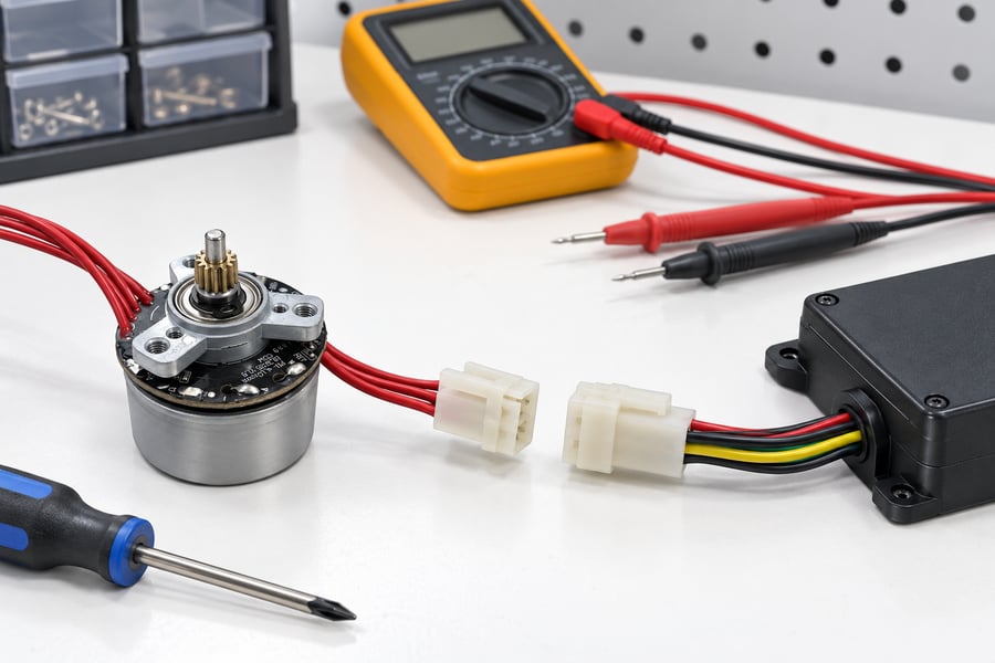
Illustrative service arrangement: accessible connectors and test points allow checks without disturbing the motor mount. Actual isolation procedures and electrical limits must follow the approved assembly documentation.
External controllers can provide convenient measurement locations when their terminals and diagnostic interfaces remain accessible. Cabinet guards and electrical safety requirements may still restrict testing.
Integrated controllers may expose status signals or communication interfaces without permitting internal power-stage measurements. Their diagnostic usefulness depends on the actual design and provided documentation.
Fault codes should be interpreted as evidence of detected operating conditions, not definitive identification of damaged hardware. An overcurrent event, for example, can have several possible causes.
Engineers should establish which measurements are available during safe maintenance conditions and which require authorized specialized procedures. Unapproved live probing should not become a routine diagnostic expectation.
What Evidence Should Be Collected Before Replacement?
A useful fault record includes the operating state, connected load, supply conditions, observed symptoms, and available controller alarms. Intermittent failures also require information about their triggering conditions.
Technicians should inspect accessible wiring, connector retention, mechanical restrictions, and permitted electrical measurements before assigning the failure to a particular field-replaceable unit.
Where available, saved operating data can distinguish repeated startup faults from faults occurring only after thermal stabilization. Such evidence can reduce unnecessary component replacement.
The maintenance record should explain why the selected unit was replaced, what alternative causes were checked, and which diagnostic uncertainties remain for subsequent investigation.
How Do Wiring and Thermal Conditions Affect Field Service?
Motor Phase Wiring and Signal Connections
External controller arrangements require electrical connections between the driver and motor. Depending on the system, these include phase conductors, position-sensor wiring, protective connections, and other interfaces.
Longer harnesses introduce additional routing, termination, and inspection requirements. Cable resistance, switching-related interference, and sensor signal integrity must be considered during electrical integration.
Integrated arrangements can reduce the length of certain motor-controller connections, but internal wiring may become difficult to inspect or repair when enclosed within the assembly.
Maintenance instructions should identify cable assemblies by function and revision. Clearly documented connections help prevent wiring errors when controllers or motors are replaced independently.
Connector Design and Service Reassembly
Detachable connectors can simplify replacement when they are accessible and appropriate for the expected maintenance frequency. Their benefit depends on reliable retention and unambiguous mating arrangements.
Connector drawings should identify pin assignments, mating-face orientation, keying, and applicable cable identification. Wire colors alone are insufficient when harness configurations may vary.
Repeated disconnection can expose damaged contacts, ineffective locks, or inadequate strain relief. Technicians should inspect these conditions rather than assuming a reconnected harness remains electrically sound.
Cable routing must also accommodate required operating movement and installation bend limits. Following service, sealing elements, cable glands, and protective covers should be restored according to approved instructions.
Thermal Conditions in Motor-Mounted and Separately Mounted Controllers
Integrated controllers may share conductive heat paths with the motor housing. Motor winding losses and electronics losses can influence the temperature distribution within the combined assembly.
The effect depends on housing construction, component placement, operating duty, and available cooling. Motor housing temperature does not necessarily represent the temperature of internal electronic components.
External controllers experience a different thermal environment. Cabinet air temperature, adjacent heat-producing equipment, mounting surfaces, and ventilation determine the conditions surrounding the electronics.
Mounting the controller separately from the motor does not necessarily provide better thermal operating conditions. Engineers must verify the installed arrangement against the applicable component operating requirements.
Checking Temperature-Related Faults
Temperature-related failures may occur only after repeated acceleration, extended loading, or operation in a warm enclosure. A successful cold startup therefore cannot establish satisfactory thermal behavior.
Troubleshooting should compare symptoms with operating duration, load changes, ambient conditions, and available temperature or protection records. Measurements must reflect the actual machine duty.
Where overheating appears related to blocked ventilation, excessive loading, or unsuitable installation, those conditions should be addressed before assuming controller hardware has failed.
Following corrective work, technicians should repeat the relevant operating conditions and record thermal behavior. Acceptance must follow application-defined limits rather than arbitrary temperature assumptions.
What Must Be Restored After Replacing a BLDC Controller?
Replacement Compatibility and Spare-Part Identification
A replacement controller must be electrically compatible with the connected motor and machine interfaces. Similar physical dimensions or connectors do not establish functional interchangeability.
Compatibility checks should cover supply requirements, winding characteristics, current capability, sensor arrangements, and relevant control interfaces. Mechanical mounting and environmental requirements also need confirmation.
Spare-part records should identify the approved controller assembly, compatible motor configuration, applicable revisions, and any restrictions on substitution. This information prevents inappropriate emergency replacements.
Where replacement involves an integrated unit, the approved part definition must clarify whether electronics, motor hardware, or both are included in the service operation.
Parameter Backup and Configuration Recovery
Controller replacement may require restoring settings associated with the motor and driven mechanism. Incorrect parameters can alter acceleration, current response, rotation direction, or protection behavior.
The controlled configuration record should include applicable motor parameters, speed commands, startup behavior, current limits, sensor settings, and communication assignments used by the machine.
Firmware compatibility must also be considered. A stored parameter set should not be assumed suitable for another controller revision without checking the applicable configuration requirements.
Backup procedures should identify the machine, controller revision, parameter-file version, and approval status. If electronic restoration is unavailable, the approved manual configuration method must be documented.
Replacement Installation and Safe Initial Commissioning
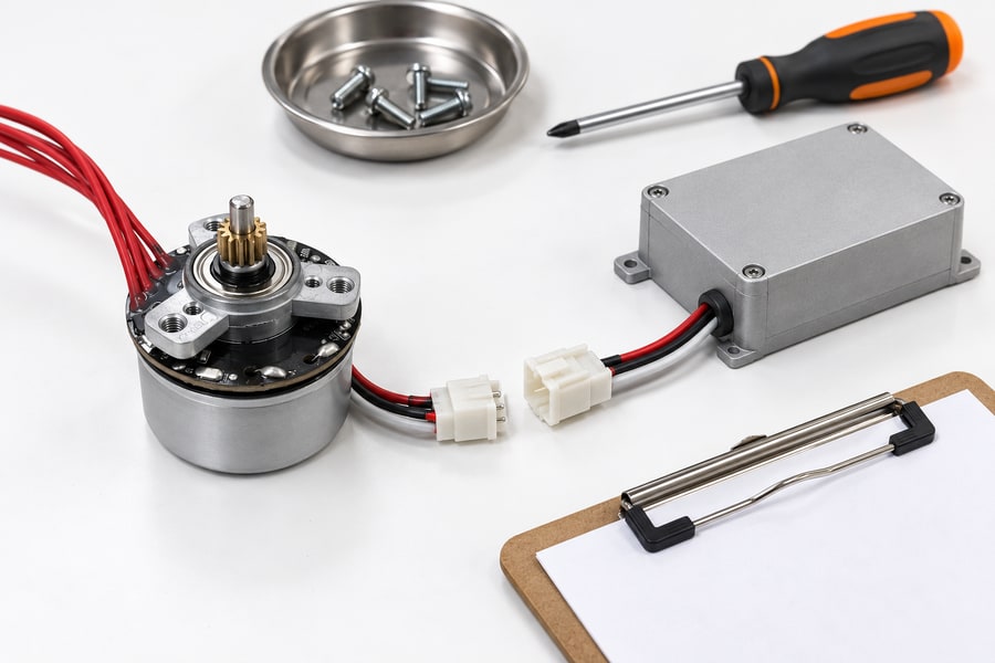
Reassembly involves connector engagement, cable support and configuration checks. The illustrated controller packaging is conceptual; service access must be verified on the actual motor and machine layout.
After replacement, technicians should verify the mechanical installation, electrical connections, protective arrangements, and restored enclosure condition before the drive is energized under approved procedures.
Initial commissioning should confirm controller identification and configuration consistency. Any mismatched settings or wiring discrepancies must be resolved before progressing to normal machine operation.
The first functional checks should verify commanded direction, startup response, and relevant feedback behavior under controlled conditions. Unexpected movement must be treated as a commissioning fault.
Machine interlocks and required safety functions need verification under their separate approved procedures. Normal controller operation alone cannot demonstrate that the machine’s safety-related functions meet their specified performance requirements.
Functional Testing Before Returning Equipment to Service
A replacement that starts successfully may still behave incorrectly under acceleration, load changes, or extended operation. Acceptance testing should therefore represent the machine’s required operating conditions.
Relevant measurements may include speed behavior, current response, position feedback where applicable, and temperature trends. The selected parameters depend on the actual control application.
Fault handling and restart behavior should be checked where required by the machine specification. These tests must distinguish controller operational responses from independently specified safety requirements.
The final maintenance record should identify the installed hardware, configuration revision, test conditions, measured results, and authorization for returning the machine to production.
| Symptom or Check | Required Evidence | Inspection or Corrective Action | Acceptance Basis |
| Motor fails to start | Supply condition, fault indication, load state | Check approved supply, wiring, configuration, and mechanical conditions | Specified startup operation under representative load |
| Intermittent operation | Fault timing, connection condition, operating records | Inspect harnesses and correlate faults with operating conditions | Required operation without the observed fault |
| Suspected sensor fault | Applicable sensor signals and configuration | Verify wiring, signal interpretation, and approved settings | Motor-specific sensor interface requirements |
| Temperature-related shutdown | Temperature history, duty, protection event | Examine cooling, loading, and installation conditions | Approved operating and thermal limits |
| Configuration restoration | Hardware revision, firmware, parameter record | Restore and verify the approved configuration | Matching controlled configuration record |
| Loaded functional operation | Speed, current, feedback, and load measurements | Test required operating profiles after replacement | Application-defined performance limits |
| Fault response and restart | Observed fault handling and restart behavior | Verify specified operational responses and applicable separate safety tests | Approved machine acceptance procedure |
Which Controller Layout Is Easier to Service in a Real Machine?
Compare a Controller Failure and a Motor Failure Separately
A practical comparison should examine controller failure and motor failure as separate maintenance scenarios. These faults may require different replacement procedures even within the same machine.
If an integrated design requires complete assembly replacement after an electronics fault, motor disconnection and mechanical reinstallation may dominate the repair despite limited external wiring.
An external arrangement may permit controller replacement without disturbing motor alignment. However, diagnosis must still account for the harness and electrical interfaces connecting the components.
For motor failures, a separately mounted controller may remain installed. An integrated assembly might require replacement of additional healthy components, depending on its approved service boundary.
Calculate the Actual Maintenance Workload
Service time should include isolation, diagnosis, component access, removal, installation, configuration recovery, functional testing, and production release. Comparing removal time alone can misrepresent maintenance effort.
Where motor removal is necessary, alignment, coupling inspection, or load-support arrangements may add work. External controllers instead may require additional cable inspections and connection verification.
Spare availability also influences restoration time. A readily available complete assembly may sometimes support faster repair than an independently replaceable controller that is not stocked.
Engineers should compare these scenarios using documented procedures and measured maintenance work. Without such evidence, controller placement provides only a preliminary indication of serviceability.
What Service Evidence Should Engineers Request?
Engineering procurement should establish maintenance requirements before controller placement is finalized. Supplier information must identify practical service boundaries, electrical interfaces, and installation restrictions.
The following records help engineers determine whether the proposed arrangement can be supported by the intended maintenance organization.
- Assembly drawings: Identify controller placement, mounting interfaces, removal clearances, and components requiring disturbance during maintenance.
- Replaceable-unit definitions: Specify approved service assemblies, part identification, and restrictions on internal repairs or disassembly.
- Electrical documentation: Provide wiring diagrams, connector assignments, isolation requirements, and available diagnostic interfaces.
- Configuration records: Define compatible hardware revisions, firmware requirements, parameter restoration methods, and controlled backup procedures.
- Maintenance procedures: Describe component removal, installation inspections, mechanical adjustments, and required tools.
- Acceptance procedures: Establish representative operating tests, required measurements, application-specific criteria, and maintenance record requirements.
Missing information should be treated as an engineering issue requiring resolution, rather than evidence that a particular controller arrangement is inherently easier to maintain.
Finalizing the Controller Layout and Service Requirements
The easier layout is the one that permits the approved replacement unit to be diagnosed, accessed, exchanged, and recommissioned with less verified work in the intended machine.
Integrated controllers can be practical where complete assemblies are accessible and replacement procedures are straightforward. External controllers can be advantageous where independent electronics replacement avoids mechanical disturbance.
Neither condition is universal. Restricted access, unavailable spares, undocumented settings, or unsuitable diagnostic interfaces can eliminate an apparent service advantage in either arrangement.
When specifying custom BLDC motor solutions from Gian Transmission, engineers should coordinate the motor’s electrical characteristics, mechanical integration, and intended driver requirements without assuming a particular controller packaging arrangement.
The final engineering release should contain an approved installation drawing, field-replaceable unit definition, electrical interface documentation, isolation and replacement procedure, controlled configuration backup, compatible spare-part record, and measured recommissioning acceptance results.