
BLDC motor phase-resistance balance should be checked across a production lot by measuring all three terminal pairs with a four-wire Kelvin method, correcting readings to a common temperature, and comparing both individual-motor imbalance and lot-level spread.
OEM engineers must verify winding connection and fixture repeatability before applying model-specific acceptance limits rather than a universal percentage.
What Should Be Measured When Checking BLDC Motor Phase-Resistance Balance?
A production inspection needs two separate answers: whether the three measured paths within one motor agree, and whether otherwise acceptable motors remain consistent across the lot.
Within-Motor Resistance Balance
For a three-terminal motor, record DC resistance between U–V, V–W, and W–U. These are terminal-pair, or line-to-line, measurements; they are not automatically individual winding values.
Unequal readings may reflect winding length, conductor cross-section, termination quality, or contact problems. Small differences also arise from the measurement system, particularly when nominal resistance is low.
The inspection should preserve each reading rather than recording only a single balance percentage. A suspiciously low U–V value, for example, deserves different investigation from three consistently elevated values.
Between-Motor Resistance Variation
For every sampled motor, calculate a representative average from its three comparable readings. Compare those averages across the lot only after addressing temperature and measurement conditions.
One unit can have closely matched terminal pairs yet sit outside the specified overall resistance range. Conversely, a lot may have stable averages but contain individual motors with unacceptable asymmetry.
Illustrative investigation: If U–V alone reads high, repeat the measurement with confirmed contacts before examining that electrical path. Do not assume the winding itself is defective from one reading.
Gian Transmission lists custom brushless DC motor configurations; inspection definitions therefore belong to the approved model and winding design, not a category-wide rule.
How Should Four-Wire Kelvin Resistance Measurements Be Performed?
Prepare the Motor and Test Setup
De-energize the assembly and discharge any external stored energy. Isolate motor terminals from the controller, supply, and other external current paths before applying the resistance instrument’s test current.
A connected BLDC motor driver can introduce semiconductor or protective paths that invalidate a direct winding measurement. Disconnecting the driver does not separate windings joined internally in star or delta.
Identify U, V, and W using the approved terminal drawing. Hold the shaft stationary, avoid recent powered operation, and establish an agreed method for estimating winding temperature.
- Instrument: Check calibration status, resolution, current accuracy, voltage range, and the procedure revision used for this model.
- Conditioning: Allow temperature to stabilize; document the stabilization criterion rather than assuming the winding equals the room temperature.
- Connection: Use clean terminals, controlled probe force, and consistent Kelvin contact locations for all three terminal pairs.
- Identification: Record the unit serial or traceability code, lot identifier, winding configuration, and test station.
Measure U–V, V–W, and W–U with Four-Wire Kelvin Connections
In a two-wire ohmmeter, the instrument senses voltage across its leads and contacts as well as the motor. Those added resistances can conceal small winding differences.
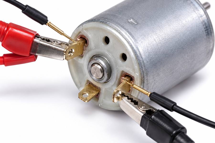
Illustrative kelvin resistance connections arrangement.
A Kelvin setup injects current through one pair of conductors while a separate pair senses voltage near the motor terminals. The measured ratio reflects the intended test path more accurately.
Use the same connection geometry for each pair. Select enough current for stable voltage resolution, but not so much that the copper warms significantly during the reading.
After settling, record voltage and current or the instrument’s calculated resistance. Repeat the sequence in a fixed order, and check that the final reading has not drifted from heating.
Control Thermal EMF and Offset Voltage
Junctions between dissimilar metals can create small thermoelectric voltages when temperatures differ. At milliohm-level resistance, these offsets may materially change an apparent DC reading.
With equal-magnitude test currents +I and −I, acquire the signed sensed voltages V₊ and V₋ before thermal conditions change appreciably. Calculate resistance as:
R = (V₊ − V₋) / (2I)
Here voltage is in volts, current in amperes, and resistance in ohms. The formula cancels an approximately constant thermal offset; unequal currents require the instrument’s appropriate correction method.
Current reversal is not a remedy for moving probes, unstable connections, changing winding temperature, or poorly timed readings. Investigate those effects separately before trusting additional decimal places.
Verify Fixture Repeatability
Measure one stable reference unit several times without moving it, then remove and reconnect it. These exercises reveal different sources of variation: electronic noise and fixture repositioning.
Where operators or stations differ, include those factors in a measurement-system study. Probe pressure, oxidation, clamping distortion, and temperature-sensor placement can otherwise resemble motor variation.
Document which resistance reading is retained after repeat testing: first result, verified retest, or a method-defined average. Changing that rule after seeing failures biases lot comparisons.
Before releasing a unit near the acceptance boundary, check whether instrument error and fixture variation could change its pass/fail classification. If a measured deviation is comparable with fixture variation, improve the method before sorting production units.
How Do Star and Delta Windings Affect Line-to-Line Resistance?
Interpret Star-Connected Windings
In a simple star-connected motor with an inaccessible neutral, current measured between two terminals flows through two windings in series. The third winding is not in that path.
For three equal winding resistances, R_LL = 2 × R_phase. Thus a terminal-pair value should not be entered into a specification calling for one winding’s resistance.
If the individual star branches are unequal but the network is otherwise simple, their resistances can be derived from the three pair measurements. For example:
R_U = (R_UV + R_WU − R_VW) / 2
The corresponding expressions follow by rotating U, V, and W. This calculation assumes no additional internal current paths and sufficiently accurate terminal measurements.
Interpret Delta-Connected Windings
A delta winding places one branch directly between a terminal pair while the other two form an alternate series path. Both paths conduct during a terminal measurement.
For three equal delta winding resistances, R_LL = (2/3) × R_phase. Multiplying every measured pair value by 3/2 is valid only under that balanced assumption.
Unequal delta branches require analysis of the actual network; they cannot be treated as three independent direct phase measurements. Record the topology before comparing values with drawing limits.
| Connection | Balanced relationship | Production interpretation |
| Star (Y) | R_LL = 2 × R_phase | Each terminal pair covers two series windings. |
| Delta (Δ) | R_LL = (2/3) × R_phase | Each pair includes direct and alternate current paths. |
| Separately accessible windings | Direct phase measurement possible | Use the specified winding terminals and isolation arrangement. |
Where the drawing names “phase resistance,” obtain its measurement definition before inspection begins. A supplier-side line-to-line result and a buyer-side winding calculation can otherwise appear contradictory despite correct measurements.
These relationships describe balanced, ideal resistive networks at a common temperature. Connections, taps, or additional internal circuitry can change what the external instrument actually sees.
How Should Copper Winding Resistance Be Normalized for Temperature?
Measure Temperature, Not Just Room Conditions
Copper resistance rises with temperature. A warm motor can therefore appear high in resistance despite having the same conductor geometry and winding quality as a cooler unit.
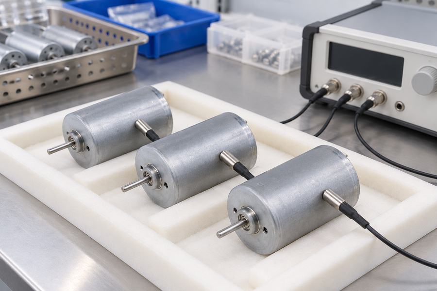
Illustrative winding temperature equilibration arrangement.
Air temperature is only a proxy for winding temperature after sufficient thermal equilibration. Recent handling, previous energized tests, and test-current self-heating can disrupt that assumption.
Define how temperature is obtained, when it is sampled, and what thermal stabilization means. For an inaccessible winding, document the validated approximation and its uncertainty.
Convert Measurements to a Common Reference
For copper over an appropriate operating range, use the linear temperature relation with a coefficient defined at the chosen reference temperature:
R_ref = R_T / [1 + α_ref × (T − T_ref)]
R_T is the measured resistance at winding temperature T; R_ref is resistance at reference temperature T_ref. Temperatures may be stated in degrees Celsius, but their difference is in kelvins.
The copper coefficient α_ref has units K⁻¹. Approximately 0.00393 K⁻¹ at 20 °C is a commonly used copper value, not an automatic substitute for an approved material and procedure.
Illustrative calculation: A hypothetical 0.520 Ω reading at 30 °C, normalized to 20 °C using α_ref = 0.00393 K⁻¹, gives 0.520 / 1.0393 ≈ 0.5003 Ω.
That example is arithmetic, not a Gian Transmission test result or product rating. Apply the selected reference and coefficient consistently, and retain the original measurement for audit.
Keep Temperature Effects Separate from Imbalance
Multiplying all three readings from one isothermal motor by the same correction factor leaves their percentage range-based imbalance unchanged. It does change absolute resistance and between-unit comparisons.
If individual windings are at different temperatures, one common correction factor cannot remove their thermal differences. Stabilize the motor or use justified winding-specific temperature information before interpreting asymmetry.
How Should Phase-Resistance Imbalance Be Calculated for Each Motor?
Calculate the Mean of Three Comparable Readings
Use the measured line-to-line values, with the same temperature convention and instrument method throughout. Calculate the average as follows:
R_avg = (R_UV + R_VW + R_WU) / 3
All resistance terms must use the same unit, normally ohms (Ω) or milliohms (mΩ). Do not combine phase-derived values from one motor with raw terminal-pair values from another.
Define a Range-Based Imbalance Percentage
Identify the maximum and minimum of those three terminal-pair readings, then divide their difference by the mean:
Imbalance (%) = [(R_max − R_min) / R_avg] × 100
Illustrative calculation: Assume U–V = 0.504 Ω, V–W = 0.498 Ω, and W–U = 0.501 Ω under identical test conditions.
The mean is 0.501 Ω and the range is 0.006 Ω, giving approximately 1.20% imbalance. This example demonstrates the formula, not an acceptable production threshold.
Specify the formula in the inspection document. A largest-deviation-from-average method yields a different percentage, so results from different definitions must never share an unlabeled limit.
Check Absolute Resistance Independently
A motor may show almost zero imbalance while all three values exceed the approved resistance range. Matching readings establish symmetry, not correctness of absolute winding resistance.
Conversely, a reasonable average can conceal one unusually high or low path. Evaluate individual readings, mean resistance, and imbalance against their respective model-specific requirements.
If a drawing states winding resistance rather than terminal-pair resistance, convert only through a verified topology and valid assumptions. Document that conversion rather than silently changing measurement definitions.
How Should the Production Lot Be Evaluated?
Define Sampling and Lot Boundaries
First identify what constitutes one lot: production run, winding batch, assembly batch, or another traceable grouping defined by the quality plan. Do not combine unlike configurations.
Choose full inspection or statistically justified sampling from product risk, process capability, customer requirements, and consequences of escape. A fixed sample count alone does not establish representativeness.
Record when samples are taken and whether they cover shifts, stations, or material changes. If production changes during the lot, the sampling rationale may need revision.
Assess Within-Motor Balance
For each inspected unit, retain U–V, V–W, and W–U measurements and calculate imbalance consistently. Flag deviations against the approved unit-level limit without rounding away borderline results.
Review which terminal pair is repeatedly highest or lowest. A recurring directional pattern may point toward a winding process or termination issue rather than random measurement noise.
Distinguish failed units from an uncertain measurement system. A repeatable rejection after controlled reconnection is stronger evidence than one unstable fixture reading.
Assess Between-Motor Spread
Compare temperature-normalized average resistance across the sampled units. Inspect the minimum, maximum, range, and, when sample size supports it, standard deviation and distribution shape.
Plot or tabulate results by production order when available. Gradual drift can signal a changing process even before the unit-level acceptance boundary has been crossed.
An unusually tight distribution also warrants scrutiny if the instrument rounds distinct values to the same display increment. Confirm that resolution is adequate before declaring a process exceptionally consistent.
Use historical data only for comparable motor revisions, temperatures, and test methods. A fixture replacement or revised normalization procedure can create an artificial step in the trend.
Make Model-Specific Disposition Decisions
Separate three questions: does each measured path meet its limit, is each motor sufficiently balanced, and does the sampling outcome satisfy the lot acceptance plan?
Set the release thresholds during design qualification, then demonstrate that the production test can distinguish acceptable windings from the defects being screened. There is no defensible universal imbalance percentage that establishes acceptance across every BLDC winding configuration.
Separately define the response to an outlying but individually passing motor. Engineering review of drift is not necessarily the same decision as rejecting a unit under a contractual limit.
When a result is borderline, apply the documented measurement-uncertainty and retest rules. Do not average repeated failed readings until an unacceptable unit appears to pass.
| Metric | Recorded result | Decision supported |
| Three terminal-pair readings | U–V, V–W, W–U in Ω or mΩ | Identify individual path abnormalities. |
| Mean resistance | Temperature-normalized average | Check overall unit resistance. |
| Within-unit imbalance | Defined percentage formula | Assess terminal-pair symmetry. |
| Between-unit spread | Range, distribution, relevant statistics | Monitor lot consistency and drift. |
| Measurement capability | Repeatability, repositioning effects, uncertainty | Support confidence in pass/fail calls. |
| Disposition | Unit status and lot decision | Authorize release, hold, or investigation. |
How Should Abnormal Results Be Investigated and Documented?
Separate Test Artifacts from Winding Problems
Start with a controlled repeat under stable thermal conditions. Check probe contact, lead routing, fixture pressure, current reversal settings, and phase-terminal identification before blaming the winding.
If the anomaly follows a fixture contact after reconnection, investigate that station. If it follows the same motor and terminal pair across verified setups, escalate electrical investigation.
Potential causes include termination resistance, conductor damage, winding length variation, and unexpected internal connections. Resistance patterns guide investigation; they rarely identify a defect uniquely.
Respect the Limits of DC Resistance Testing
DC resistance measurements can reveal opens, substantial connection problems, and some forms of winding asymmetry. They cannot certify insulation integrity or complete electromagnetic performance.
A small turn-to-turn short may cause little detectable change in terminal resistance. Balanced readings therefore cannot prove that every turn is intact or that powered torque ripple is acceptable.
Depending on design and qualification risk, complement resistance testing with suitable insulation, surge-comparison, inductance, or functional checks. Select methods for the failure modes being controlled.
Prepare Records for Engineering Handover
The record should make another engineer capable of reconstructing both the measurement and the decision. A pass stamp without conditions, raw data, or criteria is insufficient.
- Identification: Motor drawing revision, unit traceability, lot definition, connection topology, and terminal identification.
- Method: Kelvin fixture, instrument and calibration identification, test current, current-reversal procedure, and thermal stabilization conditions.
- Results: Raw terminal-pair values, measured temperature, normalized values, calculated mean, imbalance formula, and lot summary.
- Decision: Approved limits, sampling plan, uncertainty rule, retest history, disposition, and required corrective-action owner.
For a custom motor, align electrical test access and approved parameters with mechanical integration constraints during specification review. Send unresolved requirements through the Gian Transmission technical contact channel before finalizing the inspection plan.
The production handover must include the signed model-specific test procedure, reference-temperature convention, verified winding topology, acceptance limits, complete sampled-unit data, and an explicit release or hold decision.