
A linear stepper motor’s usable stroke is limited by more than the length of its lead screw. Unsupported screw length, end supports, compressive force, rotational speed and alignment can determine whether the mechanism remains stable. Select the motor and screw arrangement together, then verify the complete travel envelope.
This becomes especially important when a successful short-stroke prototype is extended for a larger machine. Keeping the same motor and screw diameter while doubling travel can change the mechanical limits substantially, even if the payload remains unchanged.
Which Part Moves in the Proposed Arrangement?
First identify whether the screw rotates, translates or remains stationary while a nut rotates. The term linear stepper motor covers different constructions, and the relevant support conditions are not identical. A drawing should show the motor, screw, nut, bearings, carriage and load path.
Gian’s linear stepper motor range provides a starting point for this discussion. Specify the required motion architecture before requesting a thrust figure, because a number without its mechanical arrangement can be difficult to apply.
A rotating screw may need evaluation for lateral vibration as speed increases. A translating screw may instead have an unsupported extension that changes throughout the stroke. Both arrangements can experience compression, but their limiting cases may occur at different positions.
The distinction from an ordinary rotary axis is explained in Gian’s linear and rotary stepper comparison. For a purchase specification, turn that distinction into an assembly sketch showing which components support each other.
Why Does Unsupported Length Matter?
A slender screw under axial compression can buckle before the motor reaches its available thrust. The relevant length is the unsupported effective span under the actual boundary conditions, not simply the catalog stroke. A carriage position change may alter that span.
Ideal Euler buckling relationships show a strong dependence on length: with other assumptions unchanged, doubling effective length reduces the ideal critical load to one quarter. That comparison explains why a longer version requires a new calculation; it is not a permissible load rating for an actual threaded assembly.
The screw’s root diameter, material stiffness and end restraint enter the assessment. Manufacturing straightness, eccentric loading and mounting errors also affect the practical design margin. Use the screw supplier’s method and allowable load rather than applying an ideal formula without correction.
MIT’s mechanical design tutorial presents column buckling as a structural design consideration. In a motorized screw assembly, the engineer must connect that structural model to the real supports and direction of loading.
Tension and compression should be distinguished explicitly. A screw pulling a load may not face the same buckling condition as the same screw pushing it, although other limits still apply. A bidirectional mechanism therefore needs both load paths reviewed.
What Do the End Supports Actually Restrain?
A bearing drawn at each end does not automatically create a fixed-fixed screw arrangement. Some supports locate the shaft radially while permitting axial movement or rotation. Others provide greater angular restraint, depending on bearing arrangement, fit and housing stiffness.
Ask the designer to state the assumed boundary condition and show how the hardware provides it. If a calculation assumes a rigidly restrained end but the production bracket flexes noticeably, the calculation and machine describe different systems. The same problem can occur when bearing clearance changes the effective restraint.
Support alignment is equally important. Adding a second bearing to a poorly aligned assembly may increase friction or force the screw to bend rather than improving operation. The support design needs tolerances, an assembly method and a way to confirm free travel.
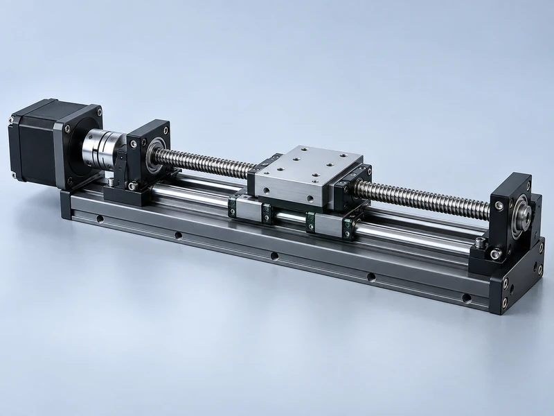
The linear guides should carry the intended side loads and overturning moments. A screw intended to provide axial drive should not be assumed to replace the carriage guidance. Show where external forces enter the platform and how those forces reach the frame.
How Does Stroke Interact With Speed?
For a rotating screw, rotational speed and travel speed are connected by screw lead. A larger lead produces more linear travel per revolution, but it also changes the force and motion relationship. Compare candidate leads using the required thrust, acceleration and motor speed together.
A long rotating screw can approach a lateral critical-speed condition. The allowable operating speed depends on its diameter, unsupported length, end conditions and the manufacturer’s design criteria. A motor’s ability to reach the commanded speed does not establish that the screw can run there acceptably.
Travel position can influence the mechanical response through changing load and support relationships. Test the full stroke instead of checking only the central section, where a prototype may happen to run smoothly. Include reversals and the longest unsupported extension.
The available torque of a stepper motor also changes with operating conditions and speed. A screw selected only from static thrust can leave insufficient acceleration margin at the intended travel rate. Match the mechanical assessment to the motor and driver performance at the actual speed.
Which Inputs Should a Supplier Receive?
A useful inquiry describes the assembly rather than asking for the longest available screw. Provide a dimensioned sketch and a duty description, then identify which features may change during design. This allows the supplier to evaluate tradeoffs instead of guessing the load case.
| Input | Detail Needed for Review |
| Stroke and overtravel | Working travel, end clearance and maximum extension |
| Axial load | Direction, peak value, duration and position dependence |
| Support arrangement | Bearing locations, restraint assumptions and bracket construction |
| Motion profile | Travel speed, acceleration, reversals and dwell periods |
| Output requirement | Allowable deflection, positioning error and settling time |
Include mounting orientation and the moving mass. A horizontal demonstration with a lightly loaded carriage cannot establish the behavior of a vertical production axis. Cable forces and attached tooling may also change over the stroke.
If the mechanical envelope is fixed, state that constraint early. It may limit screw diameter, support placement or the space available for separate guides. A supplier can then explain which performance requirements are achievable within that envelope.
How Should the Prototype Be Verified?
Begin with an unpowered mechanical inspection under an appropriate assembly procedure. Confirm support alignment, bearing seating and clearance through the intended travel. Do not use the motor’s torque to force a binding mechanism into apparent operation.
Run a staged motion test with the intended driver settings and progressively representative loads. Observe the full travel, particularly the longest extension, and measure output deflection where it affects the process. Record vibration, current behavior and any position-dependent resistance.
A positioning measurement should use a reference independent of the commanded step count. If the controller issues the correct number of pulses while the mechanism slips or deflects, the command log alone will still look correct. Compare actual carriage motion with the required result.
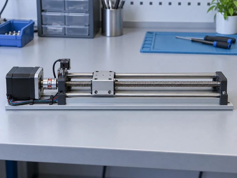
Separate mechanical stiffness from motor synchronization. Gian’s article on stepper motor inertia selection helps frame the acceleration side of the problem. A change in acceleration may improve synchronization while leaving a screw-support deficiency unresolved.
Test warm operation and repeated reversals after the basic trials pass. Friction, lubrication and structural expansion can alter the behavior seen during a brief cold demonstration. Record the operating conditions so a later design revision can be compared meaningfully.
What Should Remain in the Released Specification?
Release the screw, supports, guides and motor as a defined assembly. Record the permitted travel and load envelope, supported speed range, mounting details and any required adjustment procedure. The approved stroke should include its mechanical conditions rather than appearing as an isolated catalog dimension.
A revised bearing block, longer extension or thinner bracket should trigger an impact review. Those changes can invalidate assumptions even when the motor part number stays the same. Keep the original calculations and test configuration available for comparison.
Gian’s stepper motor size guide can help establish the motor envelope, but frame size does not resolve screw stability. Send the complete support sketch and motion requirements with the motor inquiry so the resulting proposal addresses the assembled axis.
The final acceptance should demonstrate travel under the defined load without unacceptable deflection, vibration or positioning loss. That evidence is more useful than a long screw turning freely on an unloaded bench, because it reflects the conditions the finished machine must meet.