
Torque is a key factor when choosing a BLDC motor. The problem is that a torque value means very little unless the operating condition behind it is understood.
A motor advertised with 8 N·m peak torque is not necessarily capable of delivering 8 N·m continuously. It may only sustain that output for a few seconds before winding temperature, controller current, or magnetic temperature becomes the limiting factor.
This distinction matters because many motor sizing problems start with one simple mistake:
Peak torque is treated as continuous torque.
The result may be a motor that looks powerful on paper but overheats, triggers protection, loses performance, or experiences shortened service life in the actual machine.

Peak Torque vs Continuous Torque
Continuous torque is the torque a motor can deliver for an extended period while remaining within its specified thermal and electrical limits.
Peak torque is maximum torque available briefly under high load. It is normally used to handle short-term loads such as acceleration, startup, sudden load changes, or brief mechanical resistance.
A simplified comparison looks like this:
| Parameter | Continuous Torque | Peak Torque |
| Operating duration | Long-term | Short-term |
| Typical current | Continuous rated current | Higher temporary current |
| Main limitation | Thermal balance | Current and thermal limits |
| Typical application | Steady running load | Acceleration/startup |
| Suitable for motor sizing? | Primary reference | Transient-load reference |
| Can it be maintained indefinitely? | Within rated conditions | No |
The difference is not simply how manufacturers label the specifications. It comes from how a BLDC motor produces torque and heat.
Why Higher Torque Usually Means More Current
For a BLDC motor operating within its normal range, electromagnetic torque is closely related to motor current.
A simplified relationship is:
T ≈ Kt × I
where:
- T= motor torque
- Kt= torque constant
- I= motor current
If the application suddenly requires substantially more torque, the motor normally needs substantially more current.
This is why peak torque can be several times higher than continuous torque. For a short period, the motor and controller can tolerate a current level that would be unsuitable for continuous operation.
But current has a consequence: heat.
Copper losses in the winding increase approximately with the square of current:
Copper Loss ≈ I²R
This relationship is important.
If winding current doubles, copper loss does not simply double. Under the simplified assumption of constant resistance, it becomes roughly four times higher.
That is one reason a motor can provide impressive short-term torque while being completely unsuitable for operating at that torque continuously.
Continuous Torque Is Largely a Thermal Question
A BLDC motor does not immediately reach its final operating temperature when a load is applied.
The winding, stator, rotor, housing, mounting structure, and surrounding air all have thermal mass. Heat takes time to accumulate and move through these components.
This creates temporary thermal headroom.
For example, imagine a motor with:
| Specification | Example Value |
| Continuous torque | 3.0 N·m |
| Peak torque | 8.0 N·m |
| Continuous current | 10 A |
| Peak current | 28 A |
| Maximum peak duration | 5 s |
| Rated speed | 3,000 rpm |
The motor may safely deliver approximately 8 N·m while accelerating a mechanism for two seconds.
But a machine requiring 7 N·m for several minutes is a completely different application. Selecting this motor because “8 N·m is higher than 7 N·m” would be a serious sizing error.
The correct comparison is between the actual operating torque profile and the motor’s continuous and intermittent operating capability.
Peak Torque Is Useful — When the Load Is Actually a Peak
Peak torque is not merely a marketing specification. It is extremely useful when the application contains genuine transient loads.
Consider a conveyor.
Once material is moving, the conveyor may require only 2.5 N·m. During startup, however, static friction, belt tension, material loading, and acceleration may temporarily push the requirement to 6 N·m.
The torque profile might look like this:
| Operating Stage | Required Torque | Duration |
| Startup | 6.0 N·m | 1.5 s |
| Acceleration | 4.5 N·m | 2 s |
| Normal operation | 2.5 N·m | Continuous |
| Temporary overload | 5.5 N·m | <1 s |
In this case, selecting a motor with around 3 N·m continuous torque and sufficient short-duration peak capacity may be reasonable.
Using a motor rated for 6 N·m continuously could unnecessarily increase motor size, weight, and cost.
Peak torque therefore allows engineers to size around the real load cycle instead of the single highest torque number.

Peak Duration Matters as Much as Peak Torque
A specification such as “Peak Torque: 9 N·m” is incomplete without knowing how long that torque can be maintained.
Nine newton-meters for 0.5 seconds and 9 N·m for 30 seconds are very different operating conditions.
When evaluating a BLDC motor, engineers should therefore look for:
- peak torque value;
- permitted peak current;
- allowable peak duration;
- duty cycle;
- winding temperature limit;
- controller current limit;
- cooling conditions;
- starting temperature.
The operating history also matters.
A motor starting from 25°C may have enough thermal headroom for a strong acceleration event. The same motor starting another acceleration cycle when the winding is already near 100°C may have much less margin.
This is why repeated peaks deserve more attention than isolated peaks.
Repeated Peak Torque Can Become a Continuous Heating Problem
Suppose a machine needs 7 N·m for three seconds and then operates at 2 N·m for seven seconds.
At first glance, the 7 N·m requirement appears to be a short peak.
But it occurs every ten seconds.
Over one hour, the motor experiences that high-current condition hundreds of times. The winding may not have enough time to cool between cycles, so temperature gradually rises.
RMS torque helps evaluate repeated peak loads more accurately. For several operating stages:
T_RMS = √[(T₁²t₁ + T₂²t₂ + …) / (t₁ + t₂ + …)]
For a simple cycle of 7 N·m for 3 seconds and 2 N·m for 7 seconds:
T_RMS ≈ 4.1 N·m
So although the lower-load portion is only 2 N·m, the thermal demand of the cycle is much closer to that of a motor continuously producing about 4.1 N·m than one producing 2 N·m.
RMS torque is not a complete thermal model, but it is a much better starting point than simply comparing the maximum torque value.
The Motor Is Not the Only Limit
Another common mistake is checking the BLDC motor specification while ignoring the controller.
A motor may theoretically produce the required peak torque, but only if the controller can supply the necessary phase current.
For example:
Required peak torque: 8 N·m
Motor torque constant: 0.4 N·m/A
A simplified current estimate gives:
Required current ≈ 20 A
If the controller is limited to 14 A under the relevant operating conditions, the motor-controller system cannot produce the expected torque even though the motor itself may be capable of it.
The practical system therefore has several limits:
Motor electromagnetic capability → Controller current capability → Battery/power-supply capability → Thermal capability → Mechanical capability
The lowest relevant limit determines what the system can actually deliver.
Speed Changes the Picture
Torque should also never be evaluated without speed.
At lower speeds, the motor may be current-limited and capable of relatively high torque. As speed increases, back EMF rises and available voltage margin decreases.
Eventually, the system reaches a region where the controller can no longer maintain the same current.
This means the available torque may fall as speed increases.
A motor advertised with high peak torque at low speed therefore cannot automatically produce the same torque at its maximum operating speed.
Power provides another useful check:
P = T × ω
P represents power, T torque, and ω angular velocity. Producing 5 N·m at 500 rpm is very different from producing 5 N·m at 5,000 rpm. The second operating point requires approximately ten times the mechanical power.
For real BLDC motor selection, engineers need a torque-speed operating point, not just a torque number.
Cooling Can Change Continuous Torque Significantly
Continuous torque is strongly affected by how effectively heat leaves the motor.
The same BLDC motor may behave differently when installed:
- in free air;
- inside a sealed enclosure;
- against a large aluminum frame;
- with forced-air cooling;
- near another heat-producing component;
- in a high ambient-temperature environment.
A motor mounted on a metal frame can dissipate heat more efficiently through its housing. Put the same motor inside a compact plastic enclosure with little airflow, and its sustainable continuous torque may decrease.
This is why continuous ratings should always be read together with the manufacturer’s specified test conditions.
A laboratory rating at 25°C ambient with good heat sinking cannot automatically be assumed to apply inside a 50°C machine enclosure.
Gearboxes Do Not Remove the Torque Problem
Using a gearbox can reduce the torque required directly from the motor, but it does not eliminate the need for proper load analysis.
If the output shaft needs high torque at low speed, an appropriate gear ratio can allow the motor to operate at higher speed and lower shaft torque.
However, engineers must account for gearbox efficiency, acceleration inertia, backlash, mechanical limits, and transient loads.
A gearbox should be part of the sizing calculation, not a way to compensate for an undersized motor after the fact.
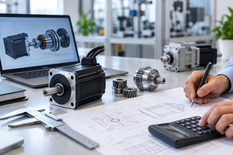
A Better Way to Size a BLDC Motor
Instead of beginning with the motor catalog, begin with the machine’s operating cycle.
Build a basic torque profile.
| Stage | Speed | Torque | Duration | Frequency |
| Startup | 0–500 rpm | 6 N·m | 1 s | Every cycle |
| Acceleration | 500–2,500 rpm | 4 N·m | 2 s | Every cycle |
| Normal running | 2,500 rpm | 2 N·m | 20 s | Every cycle |
| Deceleration | Falling | -1 N·m | 2 s | Every cycle |
Then evaluate three different requirements.
Maximum torque determines whether the motor and controller can survive and produce the transient load.
RMS or equivalent thermal torque helps determine whether repeated loads are compatible with continuous thermal capability.
Torque at speed confirms whether the required operating points remain inside the motor-controller torque-speed envelope.
After that, check voltage, current, cooling, ambient temperature, gearbox ratio, inertia, acceleration time, and mechanical safety margin.
This approach usually produces a much more reliable motor selection than comparing catalog torque values.
Do Not Oversize Based Only on Peak Torque Either
The opposite mistake also occurs.
Some engineers see a machine that occasionally requires 10 N·m and immediately specify a motor with 10 N·m continuous torque.
That can create an unnecessarily large system.
If 10 N·m occurs for only one second during acceleration while normal running torque is 3 N·m, a properly selected BLDC motor with lower continuous torque and adequate peak capacity may be the better engineering solution.
Oversizing can increase:
- motor diameter and length;
- rotor inertia;
- controller requirements;
- power-supply capacity;
- machine weight;
- installation space;
- system cost.
Good motor sizing is therefore not about choosing the largest safety margin possible. It is about placing safety margin where the actual load profile requires it.
Key Factors Before Choosing a BLDC Motor
A useful motor inquiry should contain more than “We need 8 N·m.”
The motor supplier should ideally receive the required continuous torque, maximum torque, operating speed range, acceleration time, peak duration, cycle frequency, supply voltage, available current, ambient temperature, cooling method, gearbox information, and expected operating hours.
With those parameters, the supplier can evaluate the actual operating point rather than simply matching one catalog number.