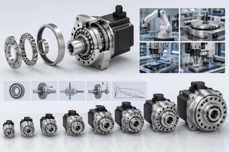
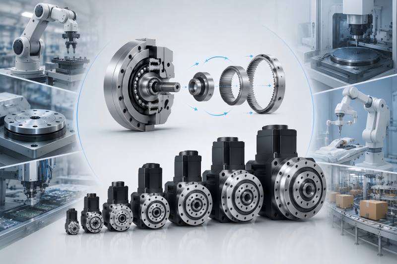
A harmonic drive motor is an excellent choice for automation equipment that requires compact structure, high torque density, low backlash, and precise positioning. However, correct size selection is essential. Engineers should not choose a harmonic drive motor only by rated torque or frame size.
A complete sizing process must consider output torque, peak torque, speed, reduction ratio, inertia, duty cycle, output bearing load, accuracy, mounting space, and thermal performance.
Why Size Selection Matters
In automation equipment, the harmonic drive motor often works under frequent starts and stops, short acceleration time, repeated positioning, and continuous load changes. If the selected size cannot handle peak torque during acceleration and deceleration, the reducer may suffer from wear or reduced service life. Harmonic Drive catalog information notes that during acceleration and deceleration, the gear experiences peak torque caused by the moment of inertia of the output load.
Correct sizing helps ensure:
- Stable output torque
- Accurate positioning
- Low vibration
- Long reducer life
- Safe operation during emergency stops
- Better heat control
- Higher equipment reliability
Common Harmonic Drive Motor Size Guide
| Harmonic Drive Motor Size | Typical Motor Power Range | Typical Torque Level | Recommended Load Type |
| Size 8 / 11 | 10W–50W | Very low torque | Ultra-light load |
| Size 14 | 30W–100W | Low torque | Light load |
| Size 17 | 50W–200W | Low to medium torque | Light to medium load |
| Size 20 | 100W–400W | Medium torque | Medium load |
| Size 25 | 200W–750W | Medium to high torque | Medium-duty load |
| Size 32 | 400W–1.5kW | High torque | Medium to heavy load |
| Size 40 / 45 | 750W–2.5kW | High torque | Heavy load |
| Size 50 | 1.5kW–3kW | Very high torque | Heavy-duty load |
| Size 65 | 2kW–5kW | Very high torque | Heavy-duty / high moment load |
| Size 80+ | 5kW+ | Extra high torque | Special heavy load |
Main Factors for Harmonic Drive Motor Sizing
Required Output Torque
The first sizing factor is output torque. You need to calculate how much torque the automation mechanism needs at the output shaft.
Common load sources include:
- Weight of the rotating arm or fixture
- Workpiece weight
- Friction torque
- Cutting, pressing, clamping, or handling force
- Gravity load in vertical-axis applications
- Acceleration torque
A simple starting formula is:
Required output torque = load torque + acceleration torque + friction torque
After calculating this value, add a safety margin. For light-duty automation, a lower safety factor may be acceptable. For high-cycle machines, vertical axes, impact loads, or 24/7 production lines, a larger safety margin is recommended.
Continuous Torque and Peak Torque
Do not size the motor only by peak torque. You must check both continuous torque and peak torque.
| Torque Type | Meaning | Why It Matters |
| Continuous torque | Torque required during normal running | Affects heat, lifetime, and stable operation |
| Peak torque | Short-time torque during acceleration, deceleration, or shock | Affects overload capacity and reducer safety |
| Holding torque | Torque required to hold position | Important for vertical axes and brakes |
| Emergency torque | Torque during sudden stop or collision | Important for safety design |
For example, a pick-and-place arm may need moderate continuous torque but high peak torque when it starts and stops quickly. If you only calculate average torque, the selected harmonic drive motor may be too small.
Output Speed
Next, calculate the required output speed. In automation equipment, output speed is usually defined by cycle time.
For example:
- A rotary table may need to rotate 90 degrees in 0.5 seconds.
- A robot joint may need to move from one angle to another in a fixed takt time.
- A camera inspection axis may need smooth low-speed motion.
The relationship is:
Motor speed = output speed × reduction ratio
If the output needs 60 rpm and the reduction ratio is 100:1, the motor speed is about 6,000 rpm before considering system limits. You must check whether the motor and reducer can safely support that input speed. Efficiency varies with ratio, speed, load, temperature, and lubrication.
Reduction Ratio
The reduction ratio links motor speed to output speed. It also affects output torque, positioning resolution, inertia matching, and system response.
| Ratio Range | Typical Use | Advantages | Possible Limitation |
| 30:1–50:1 | Higher-speed automation axes | Faster output speed | Lower torque multiplication |
| 80:1–100:1 | General precision automation | Balanced speed and torque | Common choice for many systems |
| 120:1–160:1 | High-torque, low-speed positioning | Higher torque and resolution | Lower output speed |
| 200:1+ | Special low-speed precision equipment | Very high reduction | May reduce efficiency or response |
If the ratio is too high, the output speed may be too low and the system may feel less responsive. A low ratio may require the motor to deliver higher torque.
Load Inertia
Inertia is often ignored, but it is critical for automation equipment. A large rotating load can create high torque during acceleration and deceleration.
The basic idea is:
Acceleration torque = load inertia × angular acceleration
For rotary axes, large-diameter tables, long robot arms, and heavy fixtures, inertia may dominate the sizing result. Even if the static load seems small, the motor may need high torque to accelerate the load quickly.
A harmonic drive reducer lowers the inertia load reflected back to the motor. However, the reducer itself also has inertia and torque limits, so both the motor and reducer must be checked together.
Radial, Axial, and Moment Loads
Many harmonic drive motors are connected directly to a rotating table, arm, pulley, or fixture. In these cases, the output bearing must support not only torque but also external loads.
Check these three load types:
| Load Type | Direction | Example |
| Radial load | Side load on shaft | Belt tension, side-mounted arm |
| Axial load | Push or pull along shaft | Vertical pressing or clamping |
| Moment load | Tilting load | Offset robot arm or cantilever fixture |
Some harmonic drive gearheads use cross roller output bearings to support radial, axial, and moment loads in a compact structure. If your automation axis has a cantilevered load, moment load capacity may be more important than torque capacity.
Size Selection by Application
Different automation equipment requires different sizing priorities.
| Application | Main Sizing Priority | Recommended Focus |
| Robot joint | Torque, inertia, compact size | Check peak torque and moment load |
| Rotary indexing table | Positioning accuracy, load inertia | Check acceleration torque and bearing load |
| Semiconductor equipment | Smooth motion, repeatability | Check low backlash and vibration |
| Medical automation | Compact design, quiet operation | Check noise, smoothness, and safety margin |
| Packaging machine | Cycle speed, durability | Check continuous torque and duty cycle |
| AGV or service robot joint | Weight and power consumption | Choose compact motor with efficient ratio |
| Inspection equipment | Stable positioning | Check repeatability and encoder resolution |
Practical Sizing Steps
Step 1: Define Motion Requirements
Before selecting a size, define the motion profile:
- Required rotation angle
- Move time
- Acceleration time
- Deceleration time
- Dwell time
- Cycle frequency
- Operating hours per day
Without this information, sizing is only a guess.
Step 2: Calculate Load Torque
Determine the required torque based on the load movement conditions. For vertical axes, include gravity torque. For horizontal rotary axes, include inertia and friction. For pressing or clamping axes, include process force.
Step 3: Calculate Peak Torque
Peak torque appears during acceleration, deceleration, sudden stop, or impact. This value must be lower than the reducer’s allowable repeated peak torque and the motor’s peak torque.
Step 4: Choose the Reduction Ratio
Select a ratio that allows the motor to operate within a suitable speed range while providing enough output torque.
A good ratio should:
- Keep motor speed within rated range
- Provide enough output torque
- Improve positioning resolution
- Reduce reflected inertia
- Avoid unnecessary loss of speed
Step 5: Check Continuous Operation
Even if the motor can handle peak torque, it may overheat if continuous torque is too high. For high-duty automation equipment, continuous torque is often the final deciding factor.
Step 6: Check Mechanical Interface
Check the installation dimensions:
- Motor flange size
- Output shaft or hollow shaft size
- Bolt pattern
- Overall length
- Cable direction
- Encoder space
- Brake space
- Mounting orientation
A technically correct motor is still unusable if it cannot fit inside the machine.
Common Harmonic Drive Motor Size Mistakes
Mistake 1: Selecting Only by Rated Torque
Rated torque is important, but not enough. You must also check peak torque, speed, inertia, bearing load, duty cycle, and thermal conditions.
Mistake 2: Ignoring Acceleration Time
Shorter acceleration time means higher acceleration torque. A motor that works well at slow movement may fail in high-speed cycle production.
Mistake 3: Using Too Large a Safety Factor
Oversizing may look safe, but it can increase cost, weight, and inertia. In compact automation equipment, an oversized motor may reduce machine efficiency.
Mistake 4: Ignoring Output Bearing Load
For cantilever arms and rotary tables, output bearing capacity may be the limiting factor. The reducer may have enough torque but not enough moment load capacity.
Mistake 5: Forgetting Heat and Duty Cycle
A motor used for short testing may perform well, but in 24-hour production, heat can become a serious problem. Always check actual operating duty.
Quick Harmonic Drive Motor Sizing Checklist
Before final selection, confirm the following:
- Required output torque
- Required output speed
- Peak torque during acceleration
- Load inertia
- Reduction ratio
- Continuous duty cycle
- Radial load
- Axial load
- Moment load
- Positioning accuracy
- Repeatability
- Motor voltage and driver compatibility
- Encoder resolution
- Brake requirement
- Installation space
- Cable and connector direction
- Operating temperature
- Expected service life
Example Sizing Logic
Assume an automation rotary axis needs low backlash, compact size, and accurate positioning. The table rotates 180 degrees in one second and carries a medium load.
A good sizing process would be:
- Calculate the required output speed from the motion time.
- Estimate load inertia from the table and workpiece.
- Calculate acceleration torque.
- Add friction torque and process torque.
- Choose a reduction ratio that maintains suitable motor speed.
- Check whether the harmonic drive motor can support continuous torque and peak torque.
- Check output bearing load, especially if the workpiece is offset from the rotation center.
- Add a suitable safety margin.
- Confirm mounting dimensions and driver compatibility.
This method is much safer than choosing a motor only by frame size or rated torque.
How to Select the Right Harmonic Drive Motor Size
| Motor Size | Suitable For | Typical Advantage | Selection Warning |
| Small harmonic drive motor | Small grippers, inspection heads, compact robot joints | Lightweight and space-saving | Limited torque and bearing capacity |
| Medium harmonic drive motor | Rotary tables, packaging axes, collaborative robot joints | Balanced torque and size | Must check heat in high-duty use |
| Large harmonic drive motor | Heavy robot joints, large indexing tables, industrial positioning systems | High torque and stiffness | Higher cost, weight, and inertia |
For most automation equipment, the best choice is not the smallest motor that can move the load. The best choice is the smallest motor that can safely handle continuous torque, peak torque, speed, inertia, bearing load, and duty cycle with a reasonable safety margin.