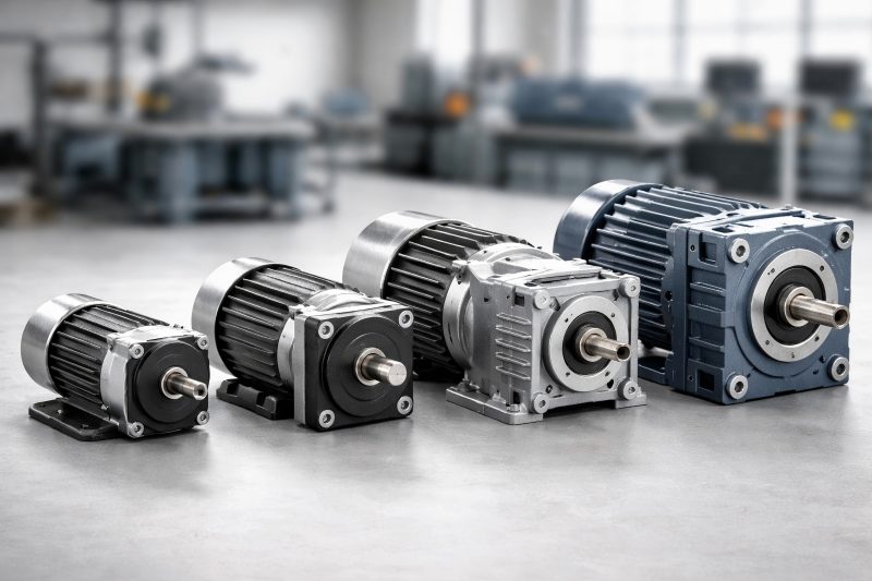
Gear motors are vital components in modern industrial applications, providing the necessary torque and speed to drive mechanical systems efficiently. Understanding their dimensions and specifications is essential for selecting the right gear motor for your project, whether in robotics, conveyors, or industrial machinery.
What is a Gear Motor?
The gear motor produces rotational motion, while the gearbox modifies the speed and torque to match the application’s requirements. Combining motor and gearbox creates compact, high-performance systems ideal for accurate and precise motion control.
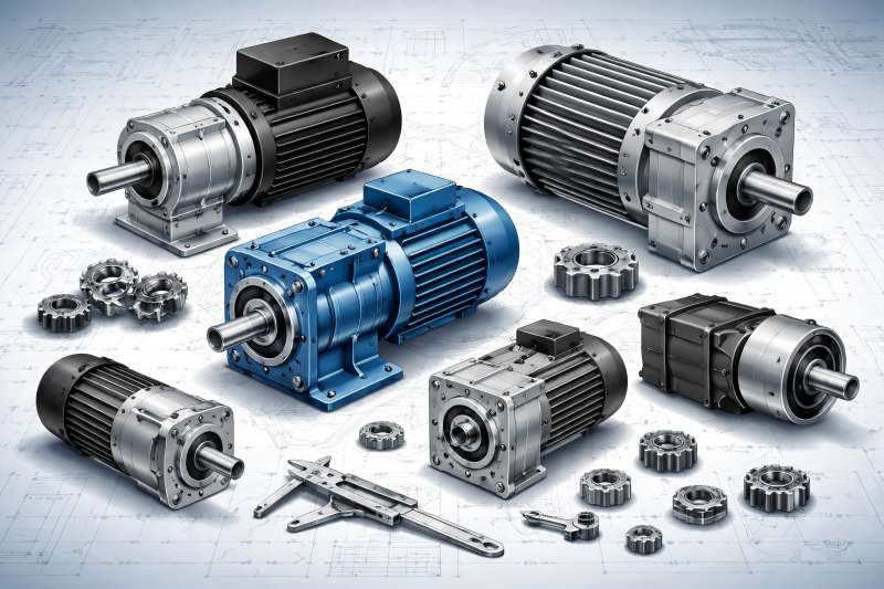
Gear motors are common in automotive, handling, automation, packaging industries. Choosing the correct gear motor requires an understanding of its physical dimensions, mounting configurations, output shaft, torque, and speed ratings.
Key Gear Motor Specifications
Before diving into dimensions, it’s crucial to understand the fundamental specifications that define gear motor performance:
Motor Power
Motor power, given in watts (W) or horsepower (HP), shows how much work the motor can produce.
| Specification | Description | Typical Units |
| Rated Power | Maximum continuous output the motor can provide | W / HP |
| Peak Power | Maximum output for short durations | W / HP |
| Voltage | Operating voltage of the motor | V |
| Current | Rated current under nominal load | A |
Speed and Torque
- Speed (RPM): Output shaft rotations per minute; gearbox lowers motor speed to achieve the desired application speed.
- Torque (Nm): Torque produced by motor; gearbox boosts torque, lowers speed.
| Gear Ratio | Motor Speed (RPM) | Output Speed (RPM) | Torque (Nm) |
| 5:1 | 1500 | 300 | 5 |
| 10:1 | 1500 | 150 | 10 |
| 20:1 | 1500 | 75 | 20 |
Efficiency
Efficiency indicates the effectiveness of a motor in transforming electrical input into mechanical output; gear motors with high efficiency reduce energy consumption and generate less heat.
Understanding Gear Motor Dimensions
Gear motor dimensions ensure correct installation and compatibility with machinery components.
Motor Housing Size
The motor housing defines the physical footprint of the gear motor. Standard housing sizes are denoted in millimeters or inches.
| Frame Size | Motor Diameter (mm) | Motor Length (mm) | Mounting Holes | Typical Power (W) |
| 42 mm | 42 | 80 | 4 | 50-100 |
| 57 mm | 57 | 100 | 4 | 100-200 |
| 90 mm | 90 | 150 | 4-6 | 250-500 |
Gearbox Dimensions
The gearbox housing dimensions vary based on the gear ratio and type. Common gearbox types include spur, helical, worm, and planetary gears.
| Gear Type | Length (mm) | Width (mm) | Height (mm) | Typical Gear Ratio |
| Spur | 80 | 60 | 50 | 3:1 – 20:1 |
| Helical | 100 | 80 | 60 | 5:1 – 25:1 |
| Worm | 120 | 90 | 80 | 10:1 – 100:1 |
| Planetary | 90 | 70 | 60 | 4:1 – 50:1 |
Shaft Dimensions
The output shaft transfers torque from the gear motor to the driven machinery. Shaft size affects the torque capacity and coupling options.
| Shaft Type | Diameter (mm) | Length (mm) | Keyway | Notes |
| Solid | 6 | 20 | 3 x 3 | Common for light-duty |
| Solid | 10 | 30 | 4 x 4 | Medium-duty applications |
| Hollow | 12 | 25 | – | Reduces weight, allows shaft coupling |
Mounting Configurations
Gear motors can be installed using various methods based on space, application.
Foot-Mounted
- Fixed with bolts to a surface.
- Provides stability and reduces vibration.
- Dimensions to note: base width, bolt hole spacing, and height.
Flange-Mounted
- Connected through a round flange.
- Allows direct attachment to the driven machinery.
- Dimensions to note: flange diameter, bolt circle, and thickness.
Inline vs Right-Angle
- Inline: Motor and output shaft share a linear axis.
- Right-angle: Shaft orientation is perpendicular, often using a worm or bevel gearbox.
- Dimensions to note: overall height, width, and depth for spatial planning.
| Mount Type | Example Applications | Key Dimensions |
| Foot | Conveyor systems | Base width, bolt spacing |
| Flange | Robotics, mixers | Flange diameter, bolt circle |
| Right-angle | Automotive, pumps | Height, width, depth |
Gear Ratio and Its Effect on Motor Dimensions
The gear ratio impacts speed, torque, and physical size of the gearbox:
- Low gear ratio: Higher output speed, lower torque, smaller gearbox.
- High gear ratio: Lower output speed, higher torque, larger gearbox.
| Gear Ratio | Output Speed (RPM) | Output Torque (Nm) | Gearbox Size |
| 5:1 | 300 | 5 | Compact |
| 10:1 | 150 | 10 | Medium |
| 50:1 | 30 | 50 | Large |
Selecting the Right Gear Ratio
- Determine load requirements (torque needed).
- Determine desired output speed.
- Match motor with gearbox to achieve these targets.
- Check space constraints for gearbox installation.
Thermal and Environmental Considerations
Gear motors produce heat during operation. Considerations include:
- Insulation class: Defines maximum operating temperature.
- Cooling method: Air-cooled, fan-cooled, or liquid-cooled motors.
- IP rating: Constructed to protect against dust and water intrusion (for example, IP54, IP65).
| Specification | Meaning | Application |
| IP54 | Protected from limited dust ingress, water splashes | General industrial |
| IP65 | Dust tight, water jets protection | Outdoor, wet environments |
| Insulation Class B | 130°C max | Light industrial |
| Insulation Class F | 155°C max | Heavy-duty applications |
Gear Motor Selection Considerations
Consider these aspects when picking a gear motor:
Load Type
- Constant load: Conveyor belts, mixers.
- Variable load: Elevators, lifts.
- Shock load: Impact machinery, presses.
Duty Cycle
It indicates the percentage of time a motor is active versus inactive during operation. This affects thermal performance.
| Duty Cycle | Description | Example |
| S1 | Continuous operation | Conveyor |
| S2 | Short-time operation | Packaging machinery |
| S3 | Intermittent operation | Robotic arms |
Application Environment
- High humidity or dust: IP-rated motors.
- Explosive environment: ATEX or IECEx certified motors.
Common Standards for Gear Motor Dimensions
Several international standards ensure compatibility and interchangeability of gear motors:
- IEC (International Electrotechnical Commission): Standardized motor frame sizes.
- NEMA (National Electrical Manufacturers Association): North American motor dimensions.
- ISO: Gear and motor mounting standards.
| Standard | Region | Key Focus |
| IEC | Global | Frame sizes, shaft dimensions |
| NEMA | North America | Motor frame, mounting holes |
| ISO | Global | Gear mounting, flanges, shafts |
Practical Tips for Beginners
- Measure twice: Always confirm mounting space and shaft dimensions.
- Check gear ratio first: Torque and speed define the gear motor type.
- Look for datasheets: Manufacturers provide detailed dimension tables and load curves.
- Account for maintenance: Allow space for servicing or replacing gear motor components.
- Verify environmental ratings: Ensure protection for dust, water, and temperature extremes.
Example Gear Motor Dimension Table
Here is an example of a gear motor catalog table showing key dimensions and specifications for different models:
| Model | Motor Power (W) | Gear Ratio | Output Torque (Nm) | Output Speed (RPM) | Motor Diameter (mm) | Motor Length (mm) | Mount Type |
| GM-42A | 100 | 10:1 | 12 | 150 | 42 | 80 | Foot |
| GM-57B | 200 | 20:1 | 25 | 75 | 57 | 100 | Flange |
| GM-90C | 500 | 50:1 | 60 | 30 | 90 | 150 | Right-angle |
| GM-90D | 750 | 100:1 | 120 | 15 | 90 | 180 | Flange |
Understanding gear motor dimensions and specifications is crucial for selecting the right motor for your application. Key considerations include:
- Motor power, speed, and torque
- Gearbox type and dimensions
- Shaft type and mounting
- Environmental protection and thermal ratings
- Industry standards (IEC, NEMA, ISO)
By carefully evaluating these parameters, beginners can make informed decisions, ensuring reliable operation, high efficiency, and longevity of their machinery. Always refer to manufacturer datasheets and consult experts if needed, especially when dealing with high-load or specialized applications.